The Philips Model BO Videosynthesizer Prototype
DISCOVERING - CLEANING - EXPLORING - TESTING/REPAIR - PARTS - SPECIFICATION DOCS - EMULATION - MUSEUM - TLDR - DOWNLOADS
At the beginning of 2021, I acquired a machine that was said to be a prototype for the Philips CD-i. Over the past few months, I’ve been working on trying to get it to boot, gathering as much information, and preserving as much about it as possible. This article will take you through that entire journey, and bundle all the information I’ve gathered so far.
Discovering and acquiring the unit
The prototype was put up for sale on ‘2dehands.be’, which can be described as a Belgian equivalent to Craigslist. It was sold alongside a CD-i 180 set and a CD-i 450. The 450 I didn’t end up getting, but I did buy the 180 set as part of the deal, which made the price tag a bit less painful. That 180 set already got its own article.
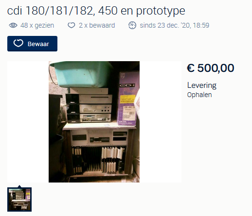
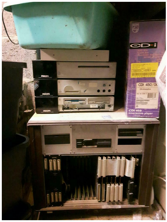
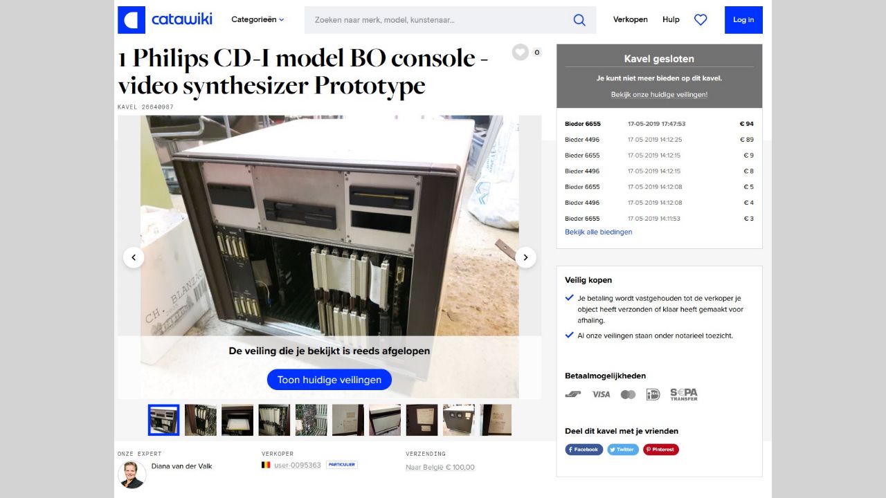
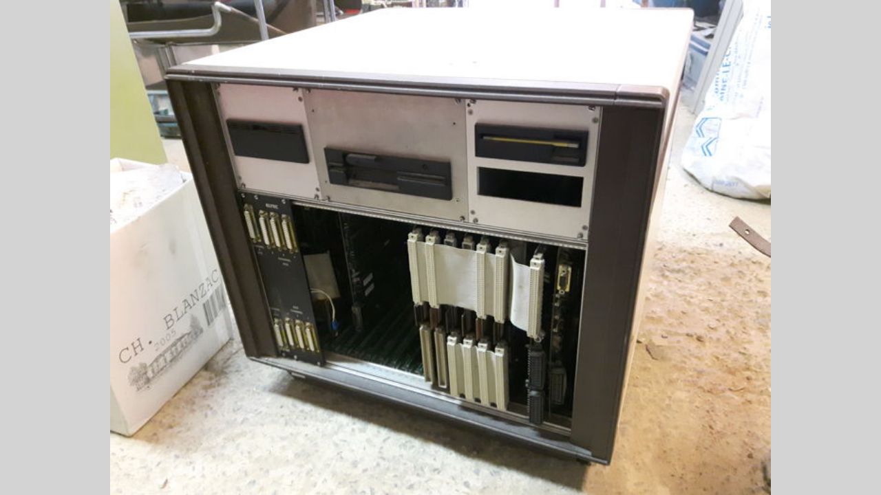
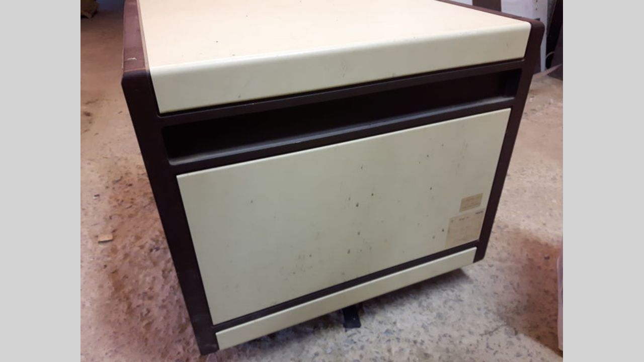
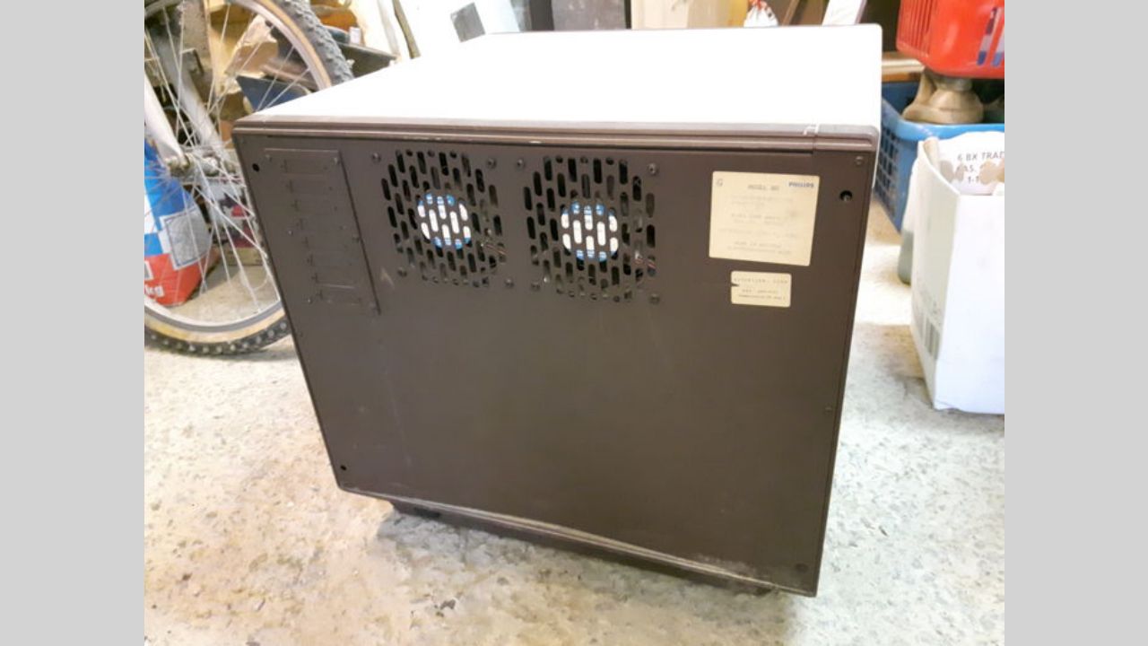
As you can tell in the image above, the seller didn’t care a lot for it. It was just collecting dust in the corner of a garage. Before contacting the seller, I did some googling around to see if this unit was ever mentioned anywhere. What I found were two things: An auction on Catawiki for what seemed to be the exact same unit, and an article on the Interactive Dreams blog reporting on said auction. Both were posted back in 2019. The auction had a lot more pictures, giving me a much better look at what this device actually was.
I contacted to seller to get some more information and to hopefully buy it. The first thing I asked about was the Catawiki listing. As I suspected, he confirmed that listing was actually his. Someone did actually end up winning that auction, but the sale never ended up happening due to a disagreement regarding shipment. After that, he lost contact with the winner, hence why he decided to put it back up for sale. I also asked what he knew in general about the device. The only thing he could tell me was: His father used to work for Philips’ CD-i division in Belgium. After that division shut down, he brought that prototype and the 180 set home with him. He also told me that only 2 of these units were ever made (which ended up being only partially true, more on this later).
We ended up agreeing on €400 for the prototype and the CD-i 180 set. The next day, I was off to Wallonia. I ended up making a visit to the Lion's Mound in Waterloo on the way, since that was close to where I had to pick it up. A fun break from the long drive! One final thing the seller told me about the unit when picking it up is that they actually used it as a coffee table for several years (seriously), which I just had to mention since it’s really funny to me.

Cleaning it up
As you probably already noticed in the images above, the unit was very dirty. Dirty might even be an understatement. It was covered in dust, oil, and all kinds of other stains. I decided not to risk turning it on before taking the entire thing apart first, cleaning and examining everything in the process.
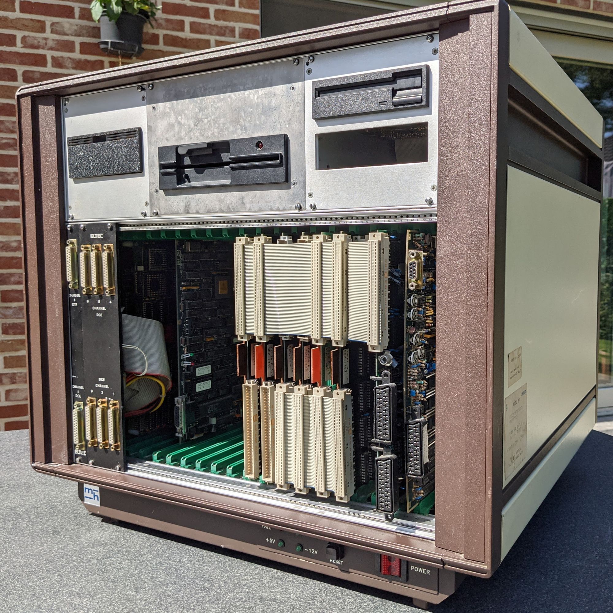
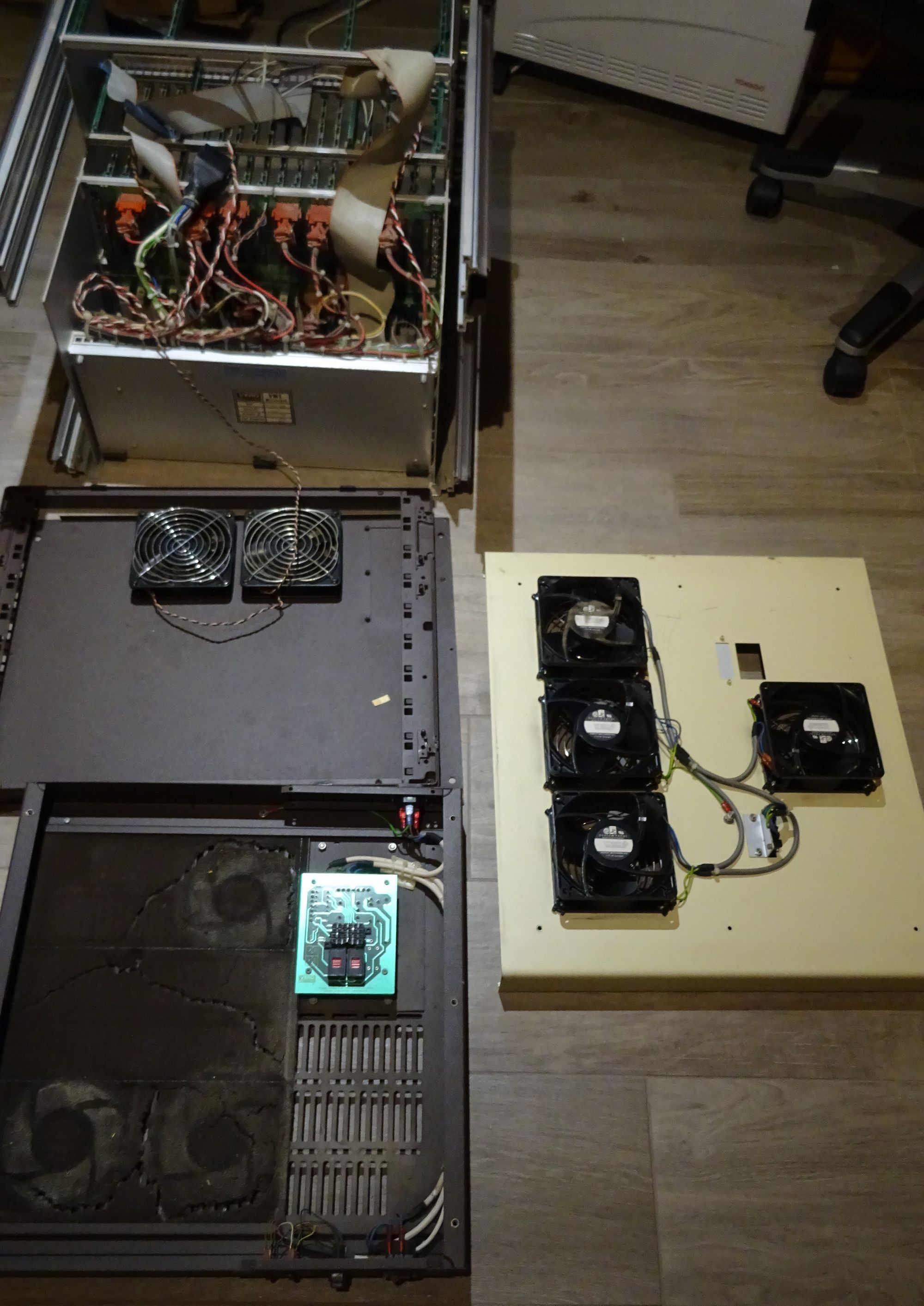
The machine turned out to be surprisingly modular. The brown pieces are plastic and the beige parts are solid metal. The back has a metal plate covering the entire side of the machine that came off after removing a few screws. After that, the front and back plastic bezels can be unscrewed and removed. With those bezels removed, I could simply slide out the metal parts. Finally the machine can be lifted from the base as a whole after disconnecting one big connector for power.
It may look and sound pretty simple, but it really wasn’t. It took me several days to get it all taken apart and cleaned, because I was documenting it and taking pictures every step of the way.
Exploring and finding out what it is
When I bought the unit, only 2 things were really known about it.
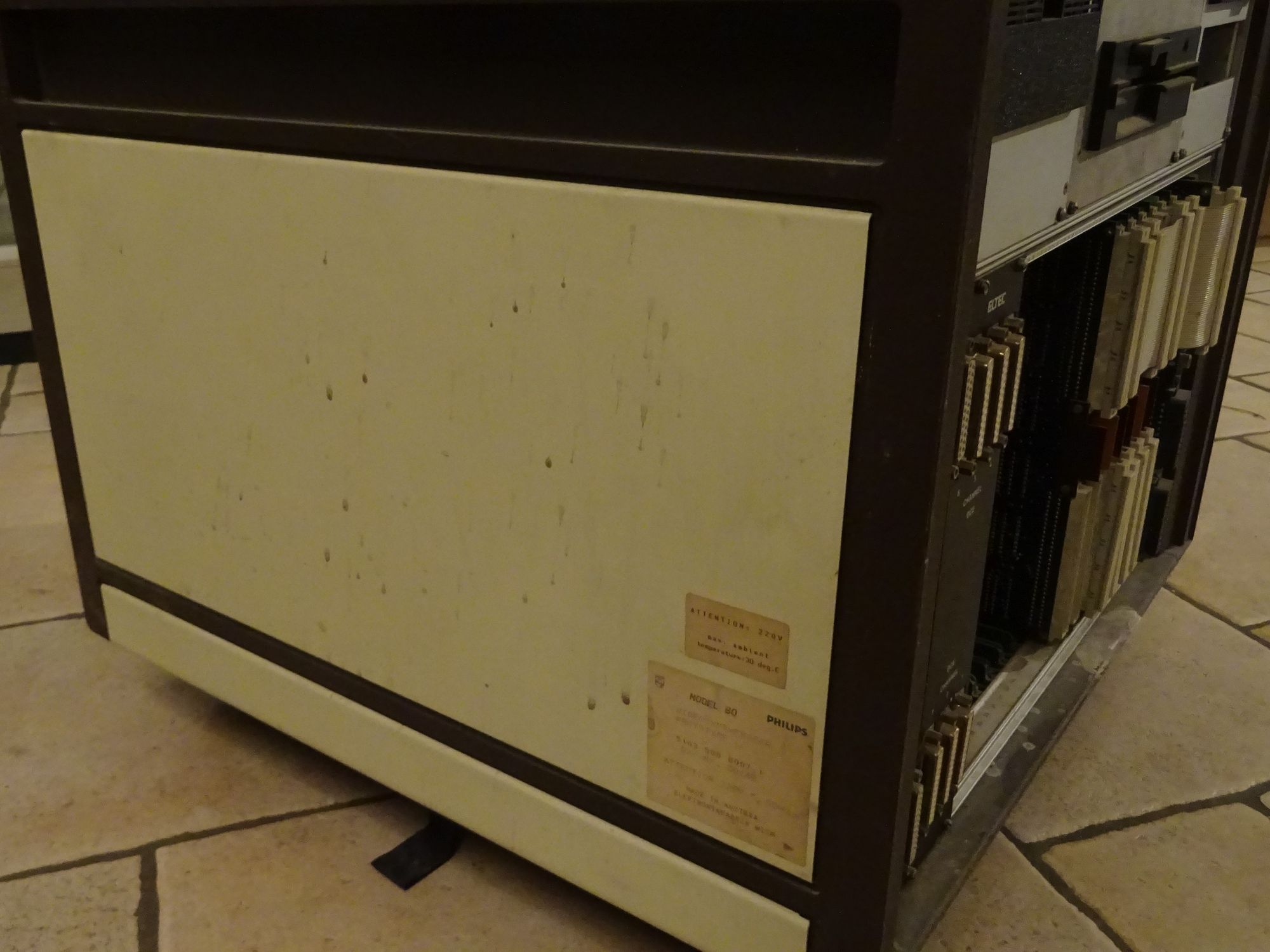
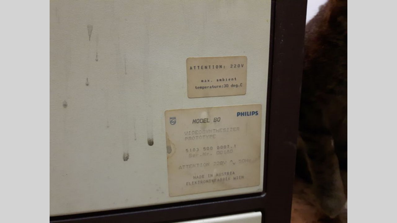
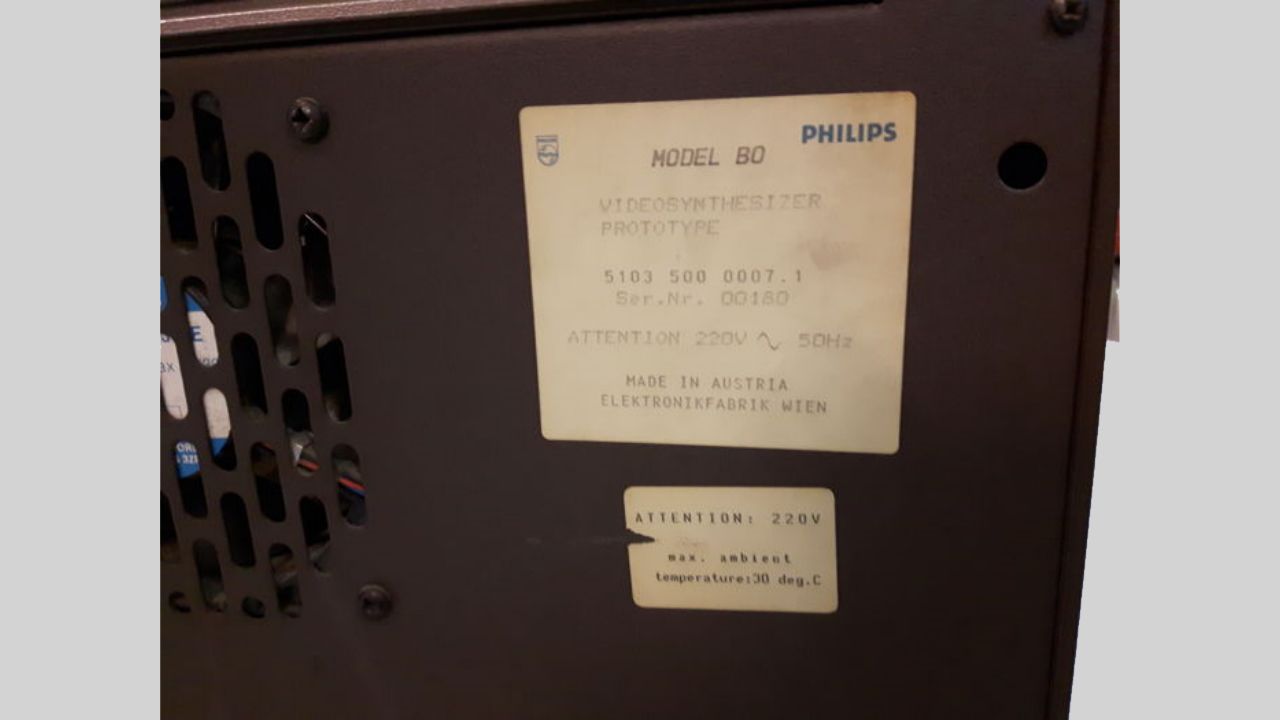
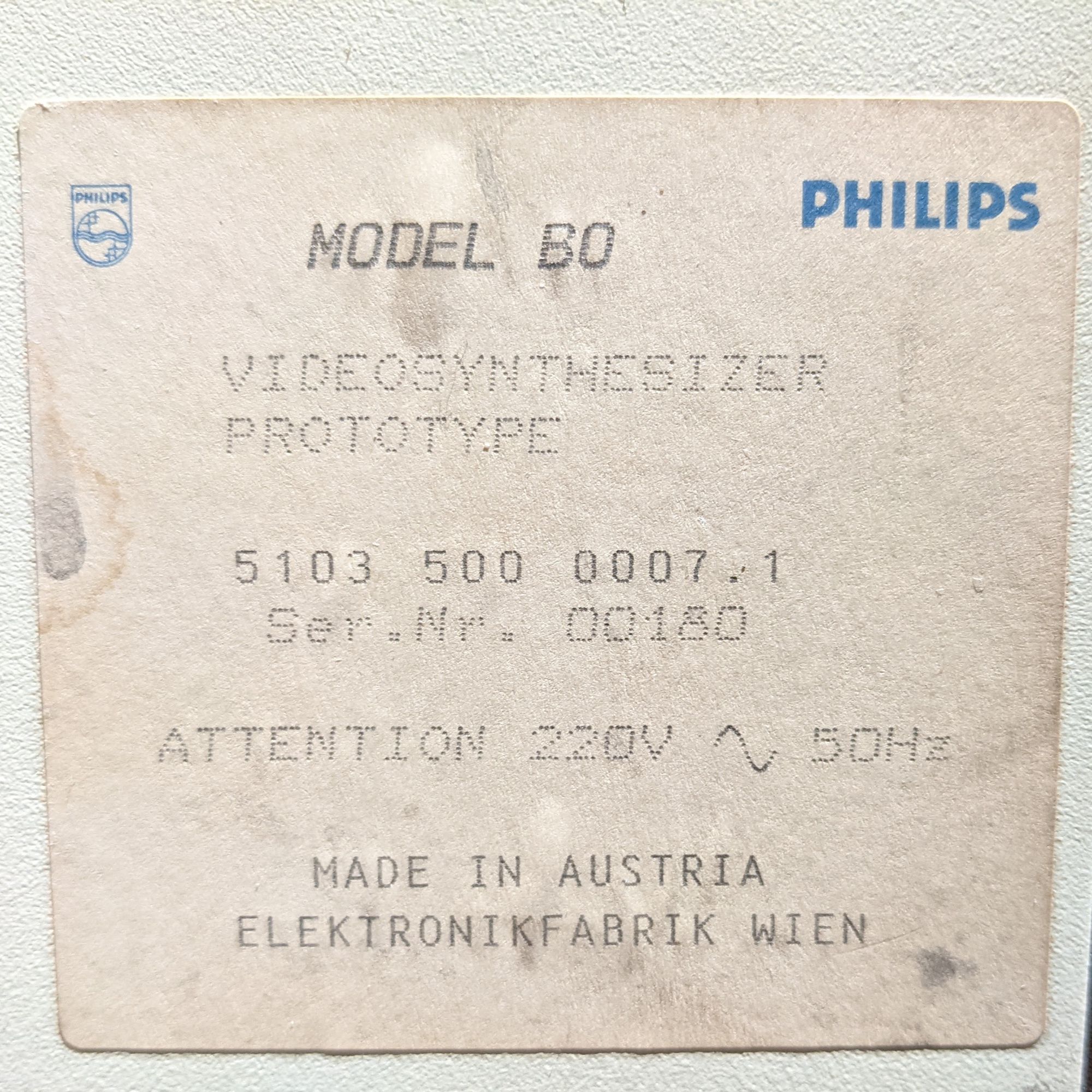
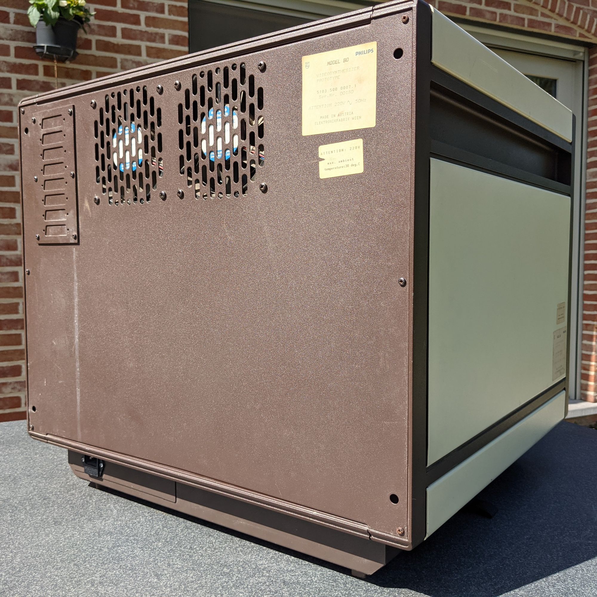
The first thing was the name, thanks to the photo of a sticker on the unit found in the Catawiki listing. “Philips Model BO Videosynthesizer Prototype”. To this day, it’s still unknown what ‘BO’ could stand for. The ‘Videosynthesizer ‘-part however, made it easy to guess that this unit had something to do with generating video signals.
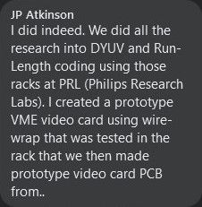
It was JP Atkinson on Facebook who was the first person to shed some light on what this unit actually is. According to him, this was a VME rack. VME was a backplane-bus-standard created by Motorola for their 68K line of CPU’s. He used this type of machine back in the day at Philips Research Labs to develop prototype video boards. These video boards would then be used to create the video IC inside the Philips CD-i.
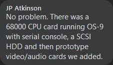
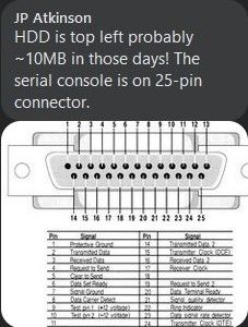
In addition to that, he was able to give some insight on the hardware. According to him, the machine has a board with a 68K CPU running OS-9 through a serial terminal. This serial terminal would be accessed through a 25-pin connector. Data was stored on a ~10mb SCSI HDD. The unit could be connected to a network using an ethernet card that was hooked up via a 15-pin connector. This turned out to all be accurate.


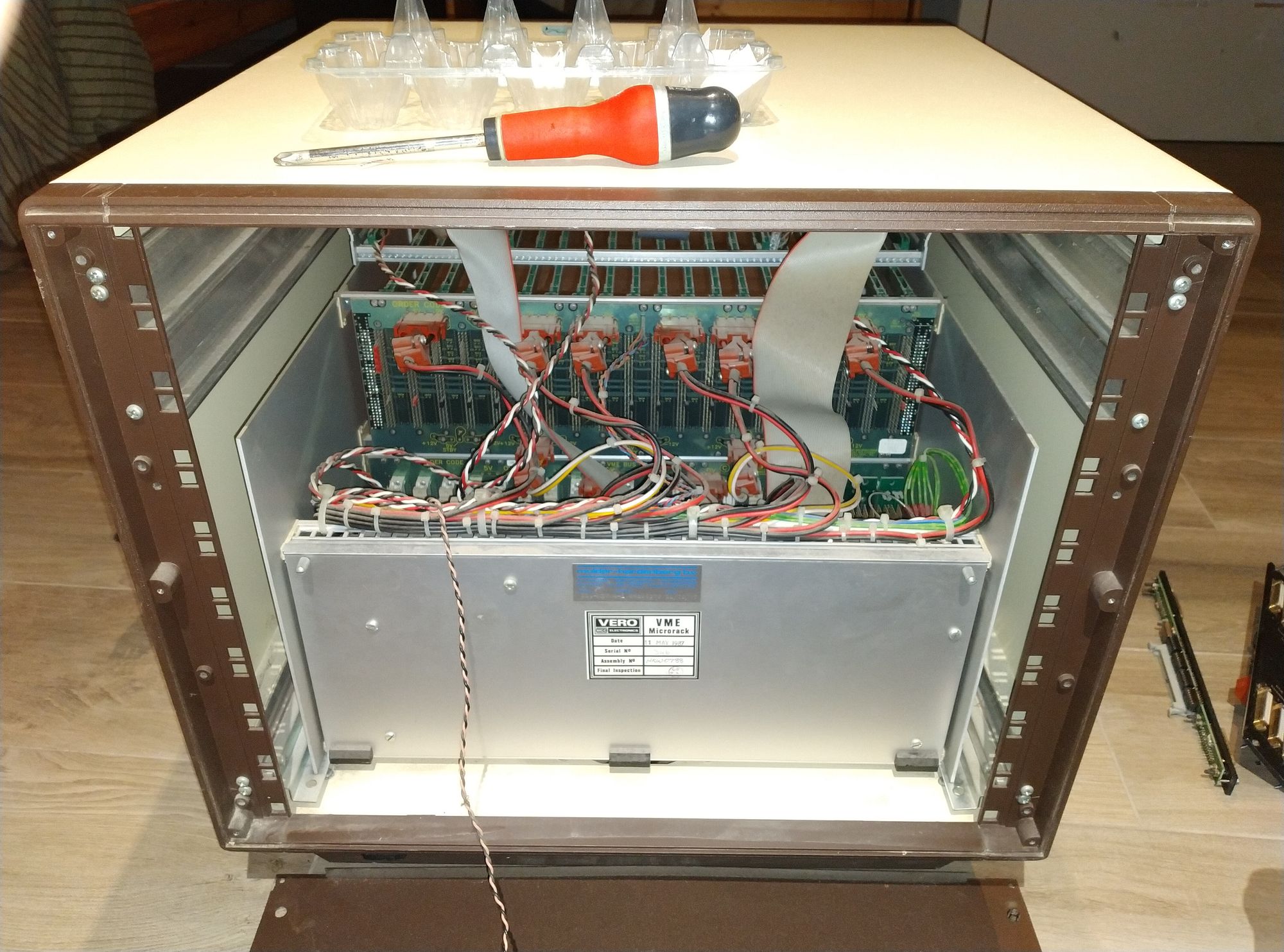
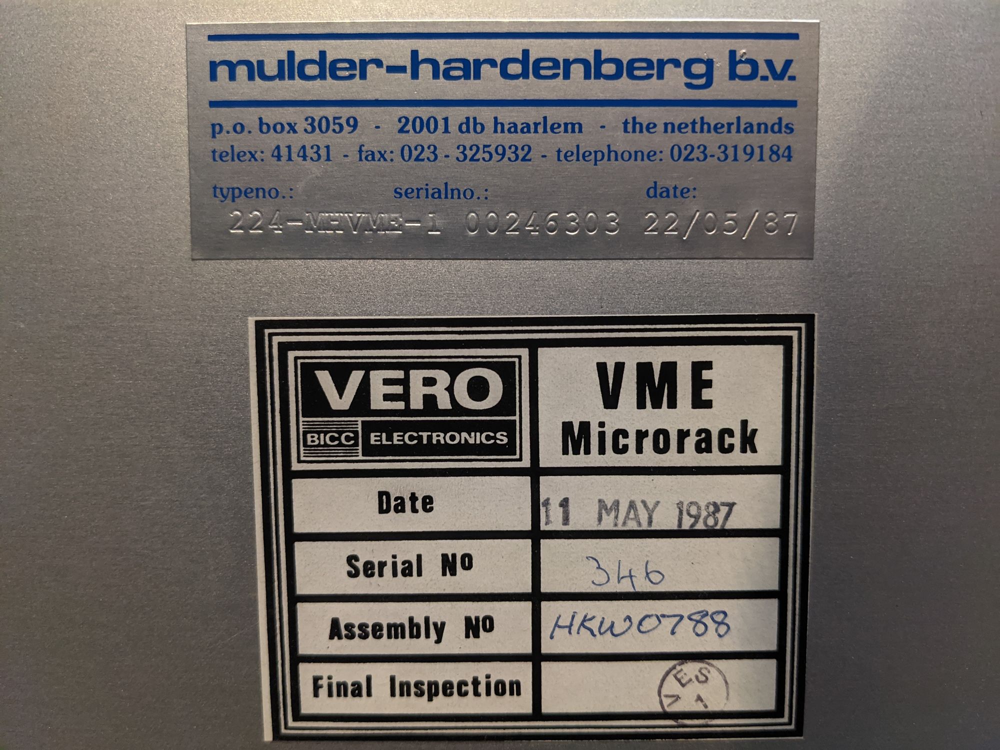
While I was cleaning everything, I could confirm a lot of details about the machine. One of the first things I noticed were two stickers on the inside of the unit after removing the back plate. These stickers confirmed that it is indeed a VME rack, made by VERO / BICC electronics, who seem to still be around to this day and be doing the same thing: making electronic enclosures. Another sticker suggests the unit was distributed by Mulder-Hardenberg, who are also still around today. They seem to be focusing on solutions for industrial installations. Both stickers also confirm a manufacturing date of May 1987. This makes sense, as that is around the time when the CD-i hardware was in active development.
One last side-note about this: The fact that all the stickers have a serial number on them makes it very safe to assume that this rack is not one-of-a-kind and likely a semi-mass-produced product. It is the video boards inside the rack that make it unique, more on this later.
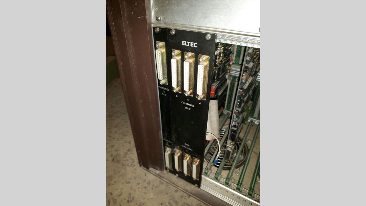
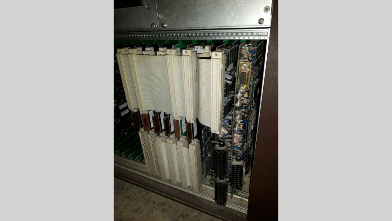
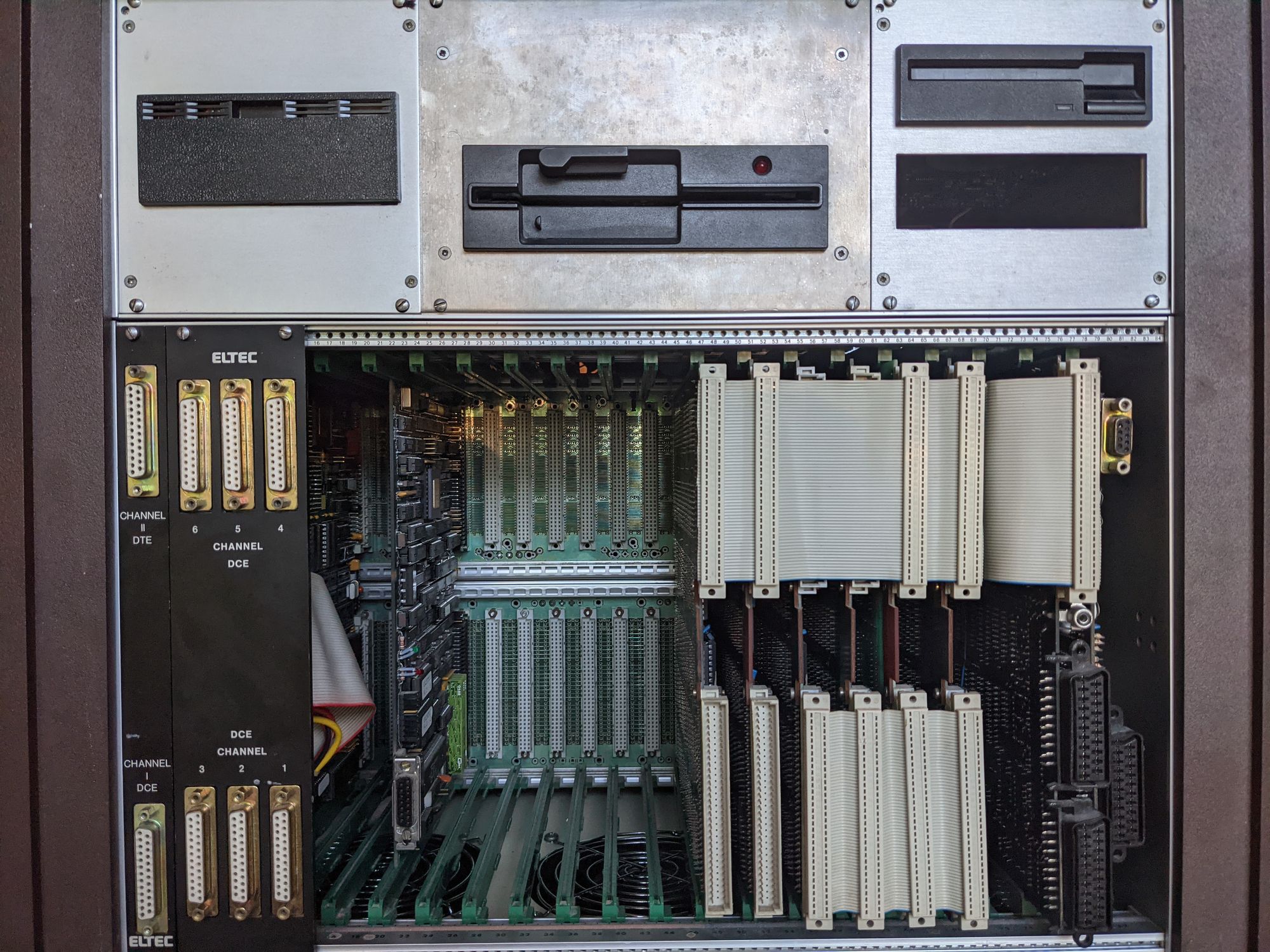
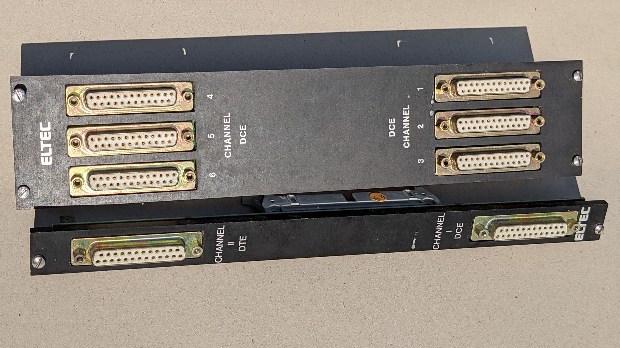
I could also confirm a lot of things JP Atkinson said. The leftmost board in the unit was indeed a board with a Motorola 68010 CPU and many other controller chips. There was a hard drive in the unit behind a brown plastic cover on the top left connected through a SCSI cable. Finally, the front of the unit had 2 brackets with multiple 25-pin connectors, one of them no doubt being used for the serial terminal.
I will be going more in depth about each part in the unit and all the specifications later in the article.
Testing & repair attempts
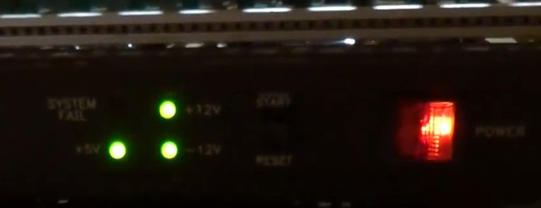
After cleaning everything, it was time to start testing things carefully. I started by turning the power supply on with nothing attached except the fans. This all went fine, the fans powered on and the LED’s on the unit indicated that all power rails were working. Just to be sure, I measured to voltages on one of the Molex connectors and my multimeter was reading correct and stable voltages. At this point, I could move on to plugging in some of the boards.
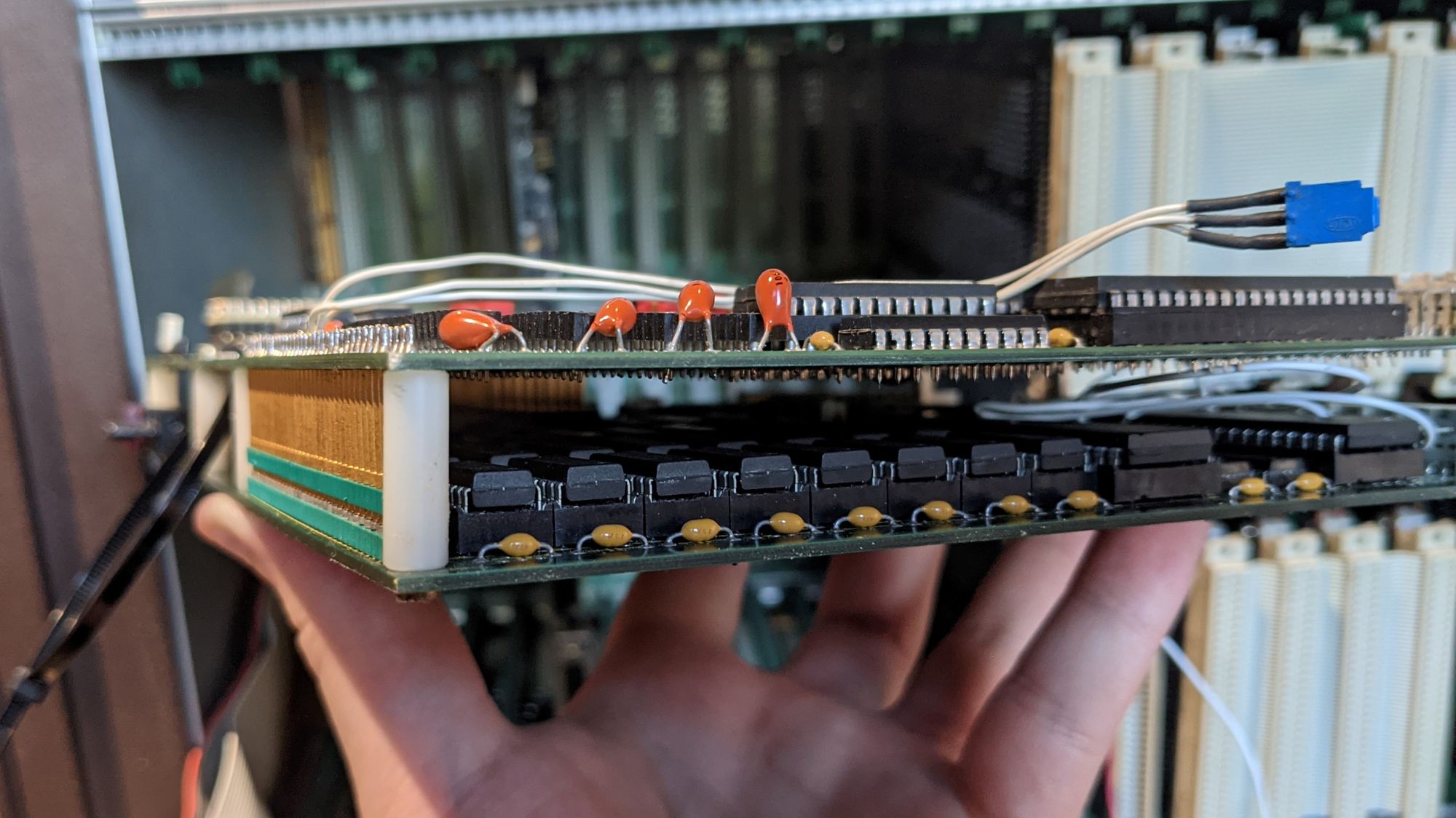
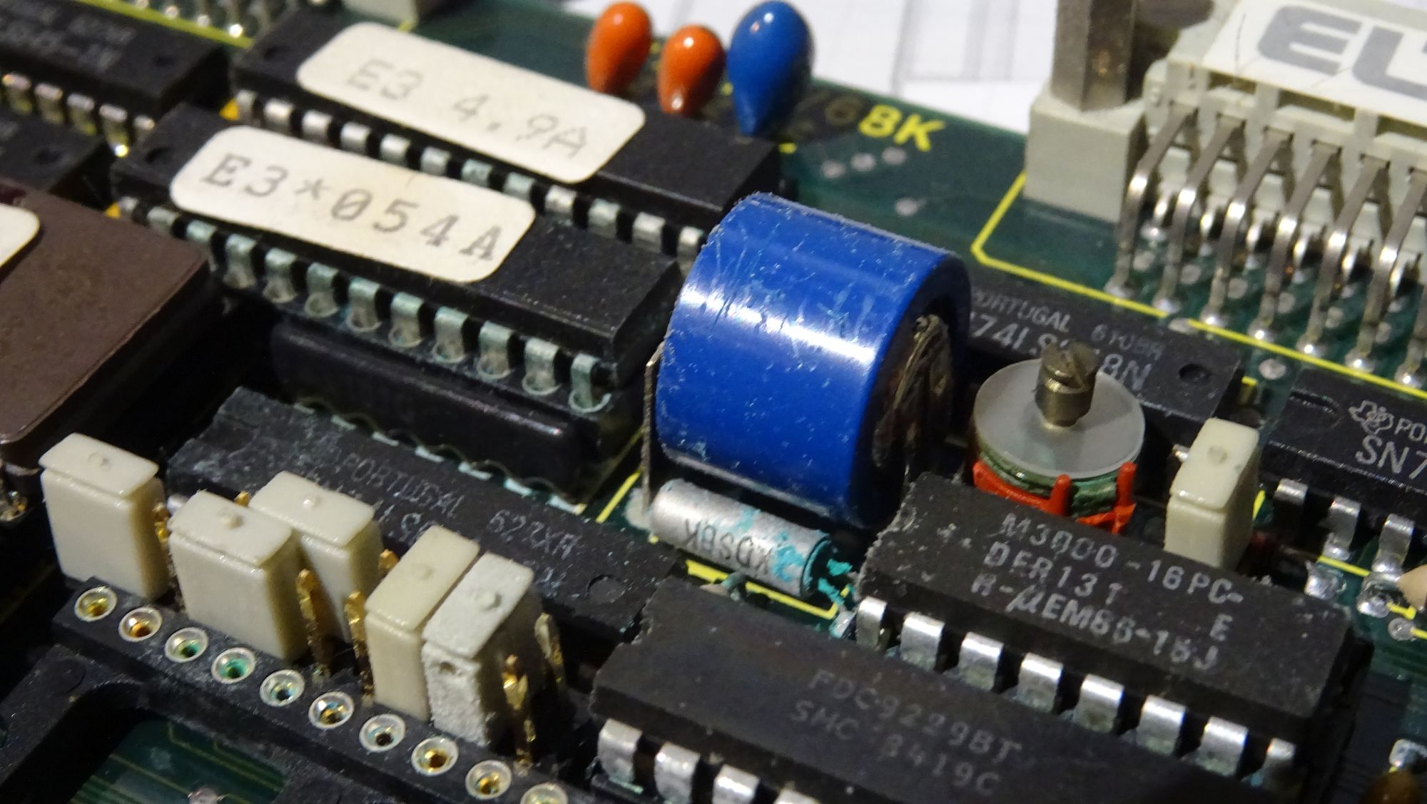
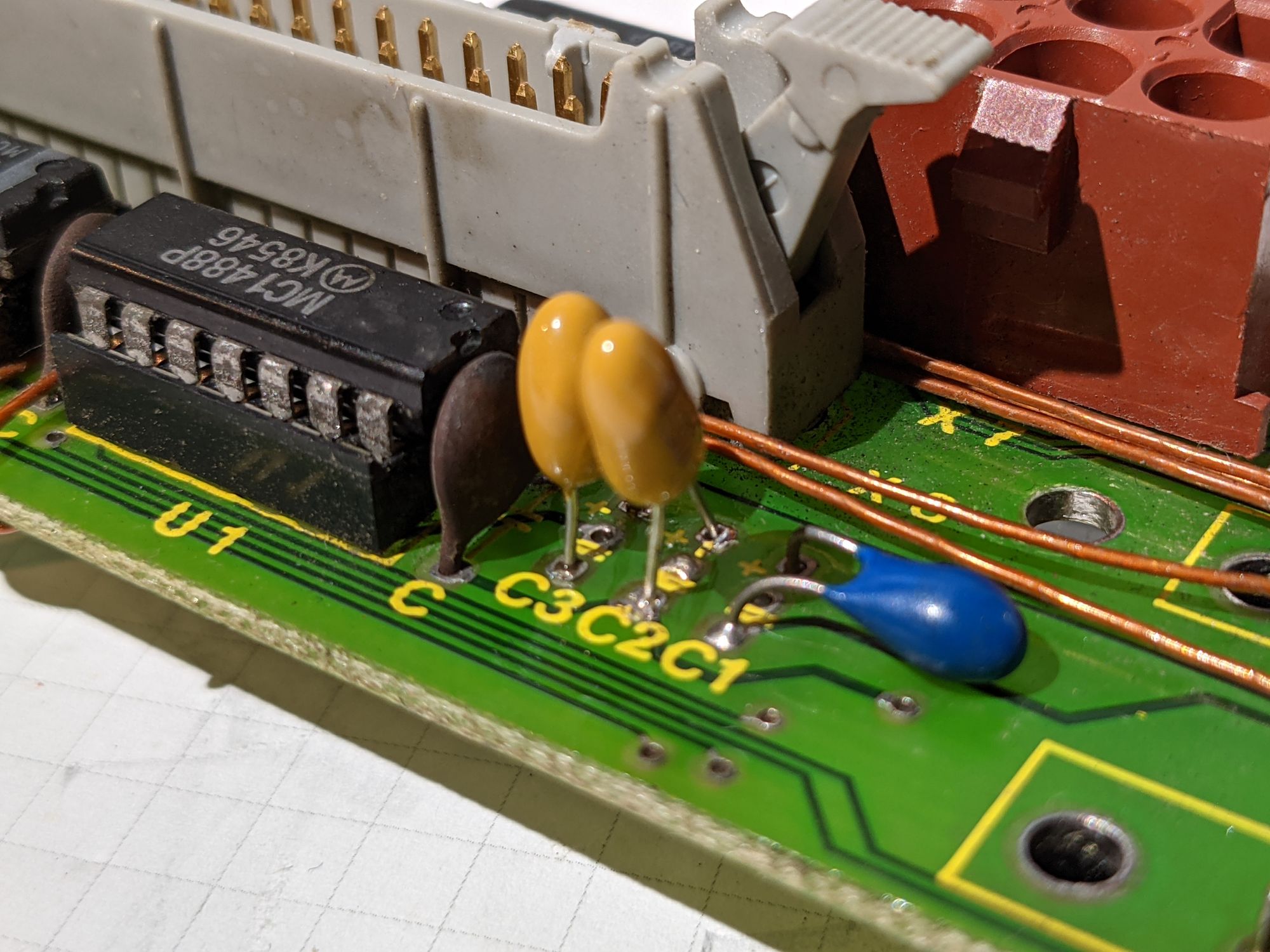
The first board I wanted to test was the main CPU board. This board is directly connected to another board through multiple pins and sockets, creating what looks like a PCB “sandwich”. However, while cleaning everything I noticed something concerning about the bottom board. A problem that is likely familiar for everyone in the retro PC scene: a leaking 'barrel' battery, used for keeping time. At first the damage didn’t seem too severe, but after separating the two CPU boards, the amount of damage became much more clear. The battery had leaked and corroded almost every component next to it, including multiple chips and their sockets, a crystal, a trim capacitor and the traces underneath.
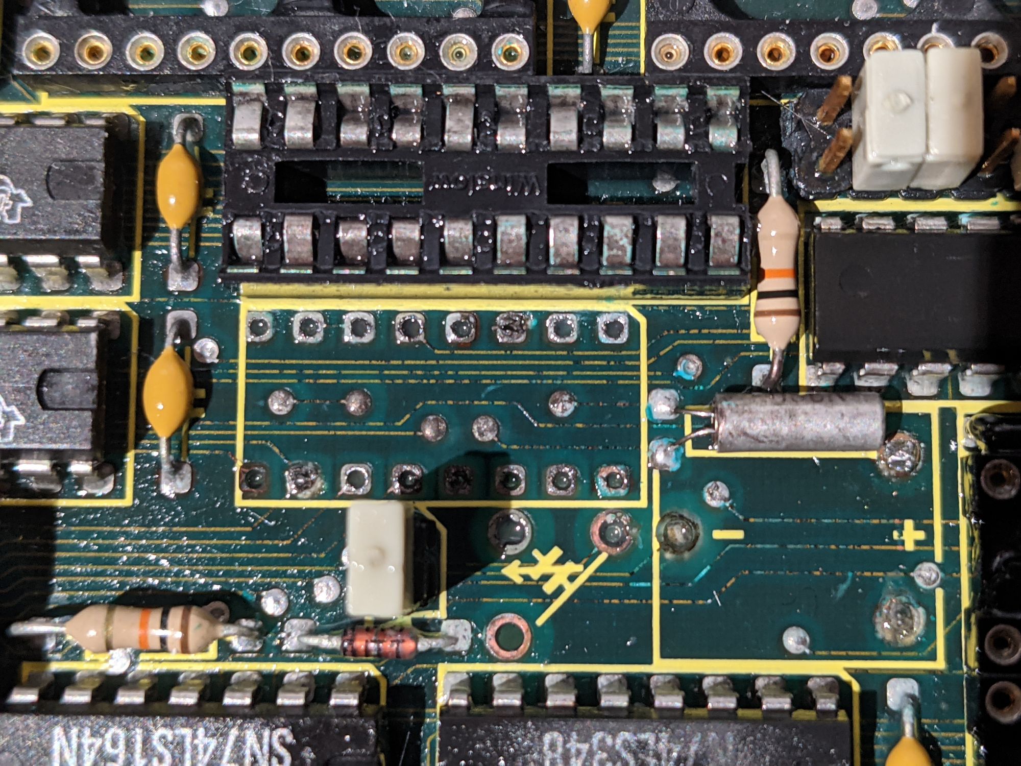
Before even thinking about powering this board on, I had to remove this battery. I carefully desoldered it and removed any corrosion with a combination of vinegar and isopropyl alcohol. It quickly became obvious that the traces around the battery were severely damaged.
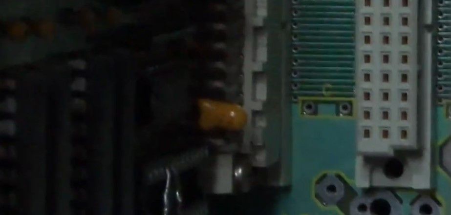
After removing only the battery and the surface corrosion (the image above was taking later down the line), I decided to put the CPU boards and the network card in the unit and test them out. I inserted the boards, turned on the power, and less than a second after flipping the switch, a tantalum capacitor blew up. This gave me quite the scare.
Not to worry though, it was an easy replacement.
After that cap was replaced, I installed the board again and tested it out. It didn’t seem to do much except display the number 1 on it’s hexadecimal display. At least it didn’t blow up this time.
I installed the network card next to see what would happen. Things powered on fine and the board’s “RUN” LED even came on, indicating it’s working.
I added back the video boards and those also powered on without anything blowing up, but also didn’t do anything.
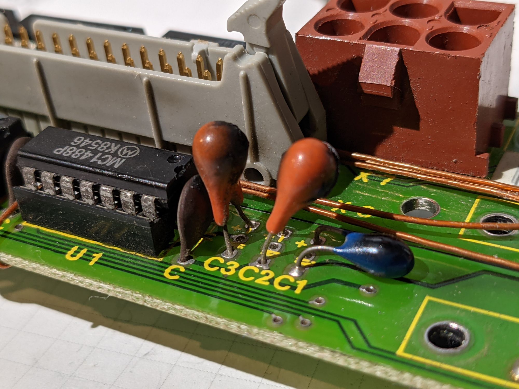
I hooked up the Floppy drives and serial ports to see what difference that would make. A few seconds after powering the unit on with those attached, one of the capacitors on the serial bracket started smoking. Another quick fix, fortunately.
I attached the HDD after first dumping it’s contents, more on this in the next part. This also did not make a difference.
Sadly, this is where I hit a massive roadblock. It became clear quickly that the unit would not be able to do anything without the main CPU board working. I spent days, weeks even trying to get this CPU board working.
Here’s what I tried:
- Poked around with a multimeter for hours, bridging any traces with wires that were not having continuity due to the battery leakage.
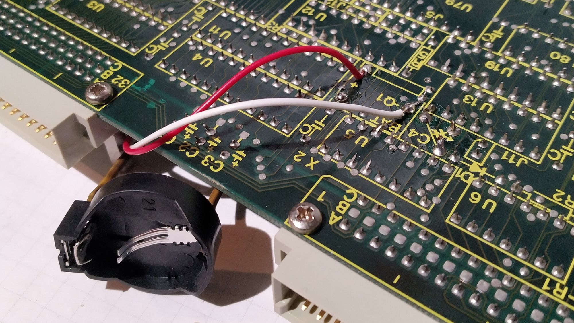
- Soldered in a CR2032 holder with battery.
- Re-seated any socketed chips
- Replaced the corroded trimmer capacitor.
- Desoldered the chips with corrosion and replaced their sockets if there were any.
- Connecting to the serial terminal with multiple cable types, multiple serial settings, and a serial signal tester. Nothing seemed to connect to the terminal successfully.
You have to keep in mind that without any documentation or schematics, this repair was seeming more and more impossible or at least incredibly difficult. I looked all around the internet for any documentation on this board but simply could not find any, despite it being a standard design by Eltec. I even tried mailing Eltec themselves, but they did not have any information.
At this point, I decided to leave the unit as-is and focus on getting as much information and data out of it as possible. And this was very successful, even if the unit doesn’t work I managed to find out a ton about it. In the next part, I’ll be going over every single detail.
In depth look at every part
Chassis, backplane and PSU
The chassis of the machine is made by VERO electronics and distributed by Mulder-Hardenberg. According to the dates on the stickers inside the unit, it was made in may 1987.
It’s mostly made out of metal, except for the frame, which is plastic. Not counting the foot, the unit is a near-perfect cube of 50x50 centimetres.
The front is mostly open in order to easily plug in VME cards. The back is covered by a big solid metal piece that can be removed with a few screws to get easy access to the power supply, the back of the backplane and drives. The sides have grooves/handles to lift the system.
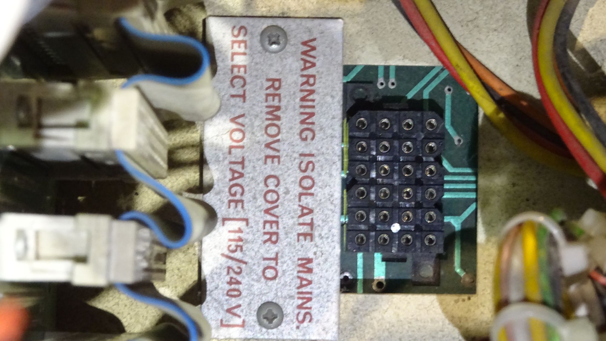
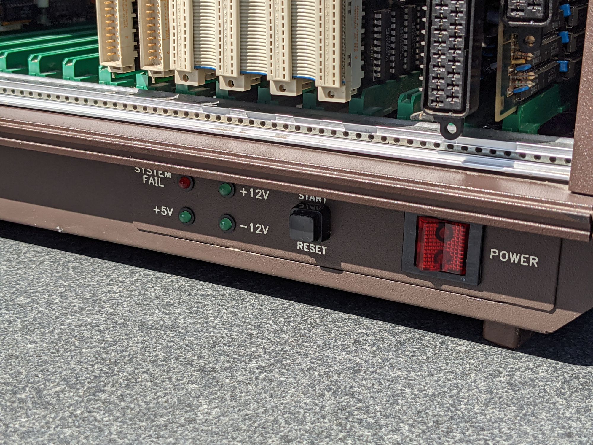
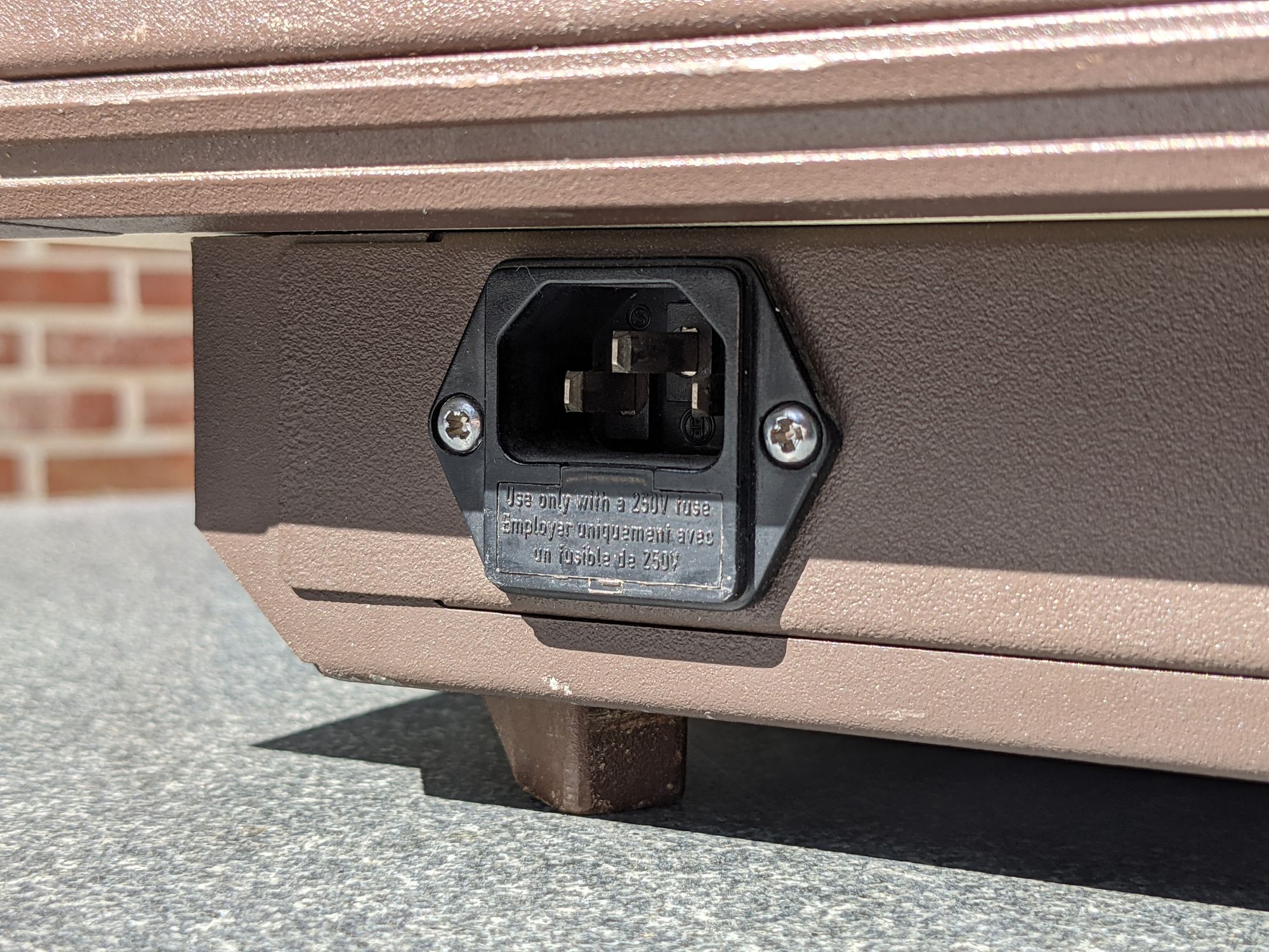
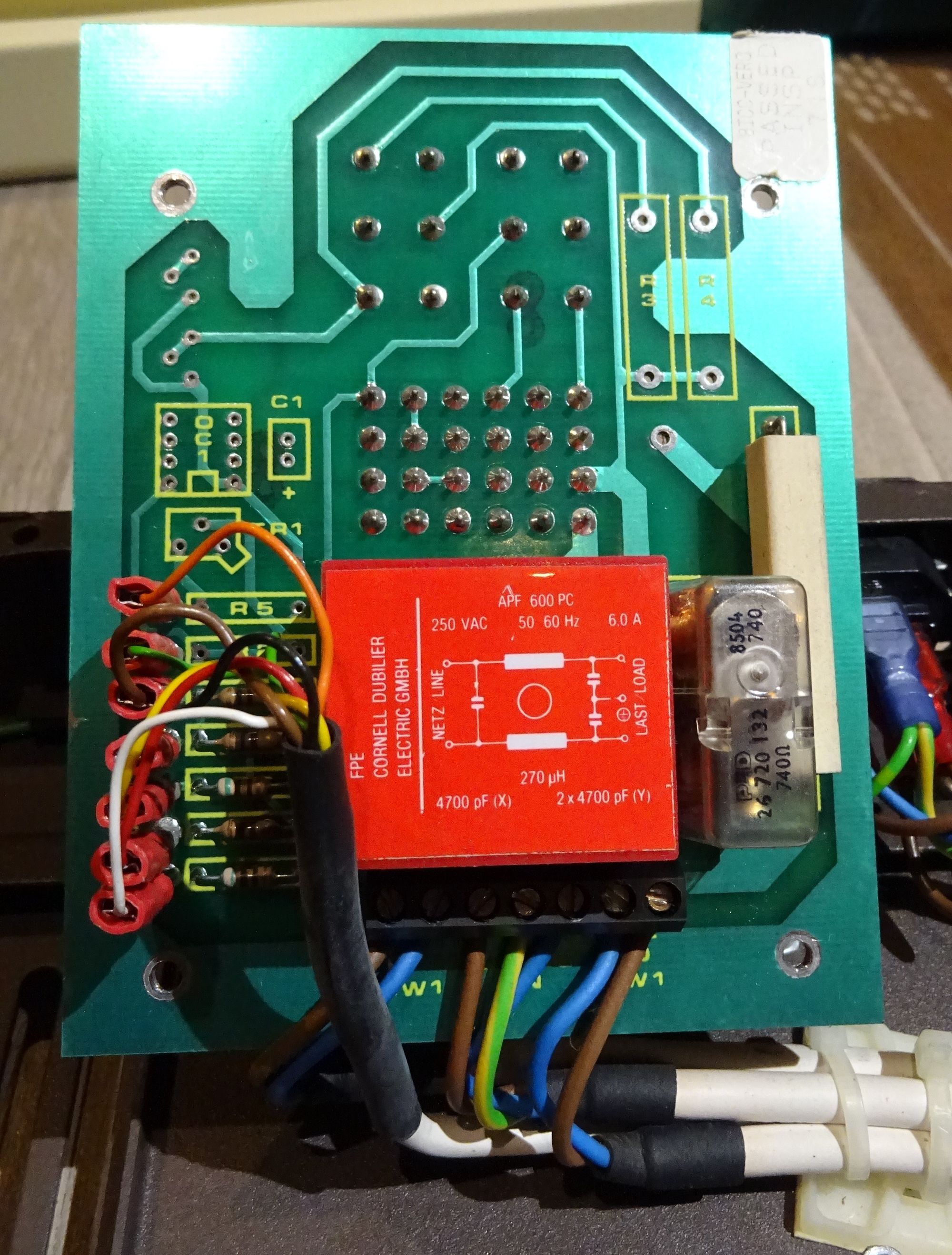
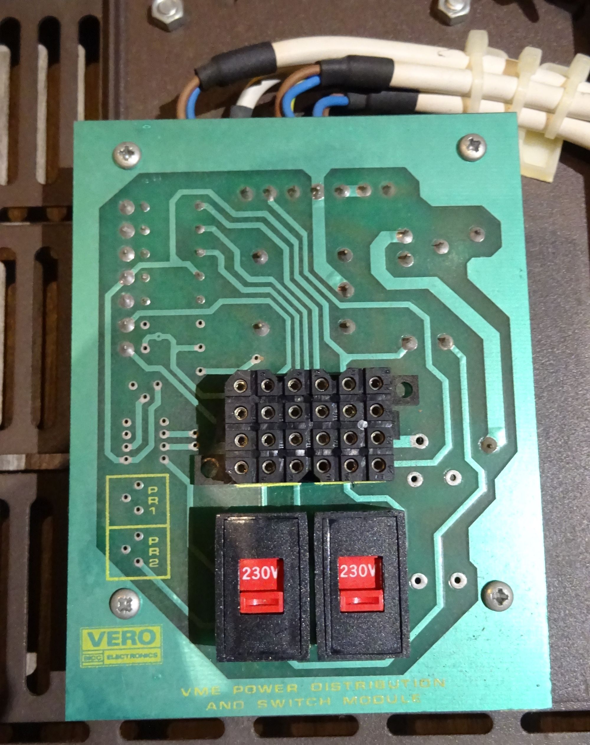
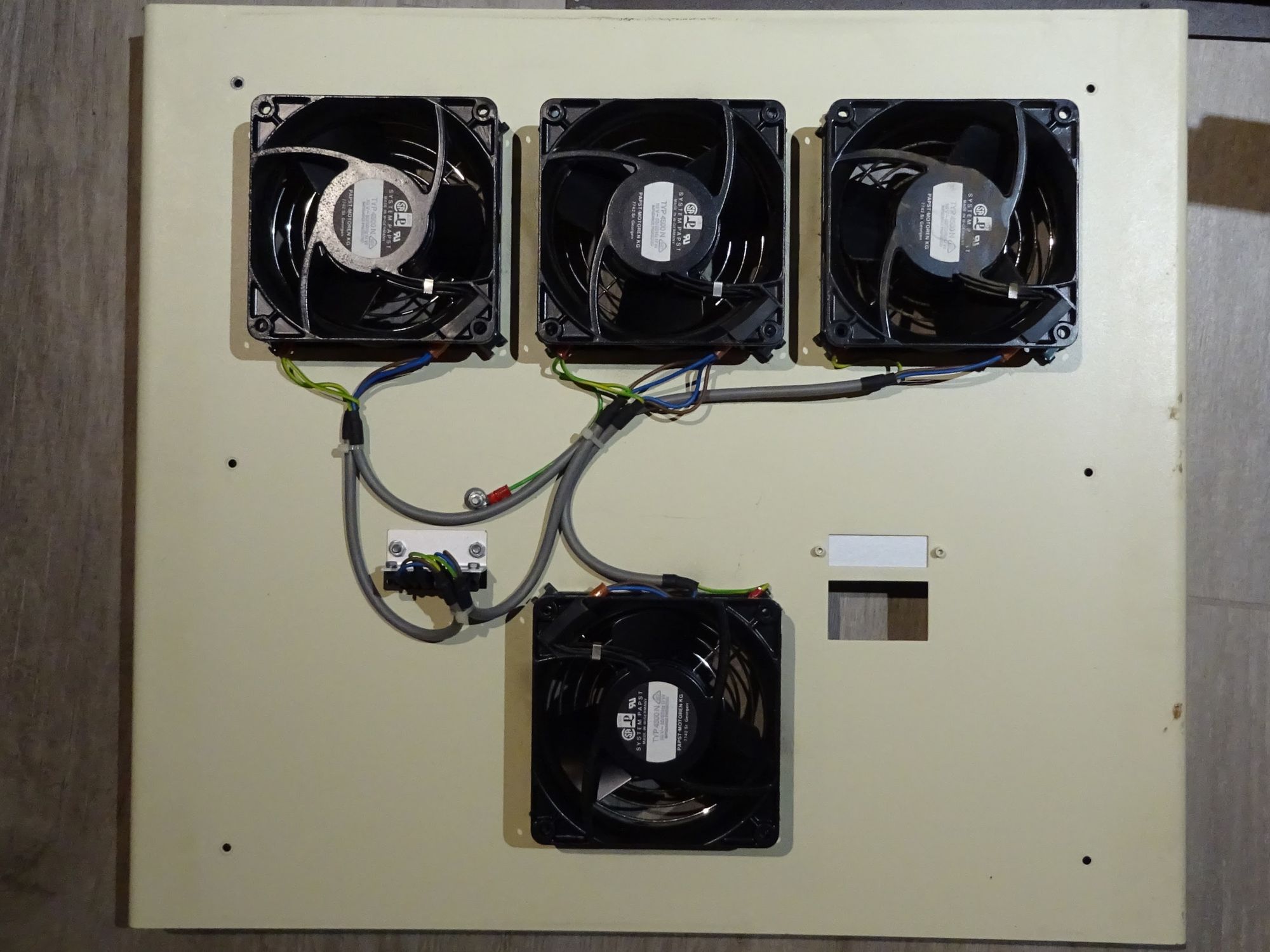
The foot of the unit contains a few components such as a small circuit board for switching between 120v/230v labelled 'VME power distribution and switch module', and the power plug, which is a standard C13 plug. On the front there’s a big red power switch, a reset button, LED’s indicating whether all voltage rails are working, and a system fail LED. Lastly, there’s 4 big fans. These fans are above a removable dust filter that one can slide out of the side. This filter’s foam had to be removed since it disintegrated upon touching it, creating quite the mess.

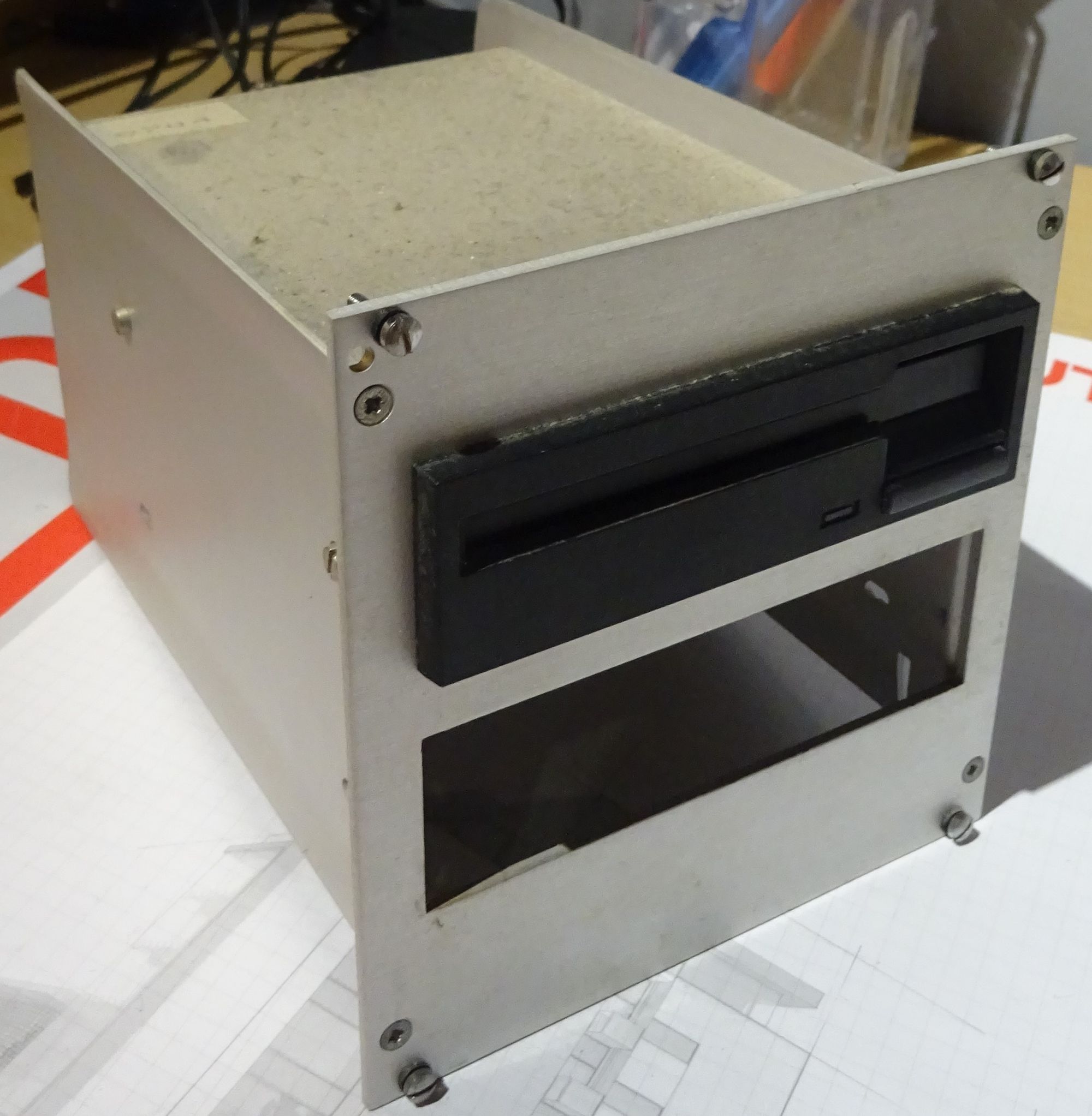
Floppy drives & boot diskette
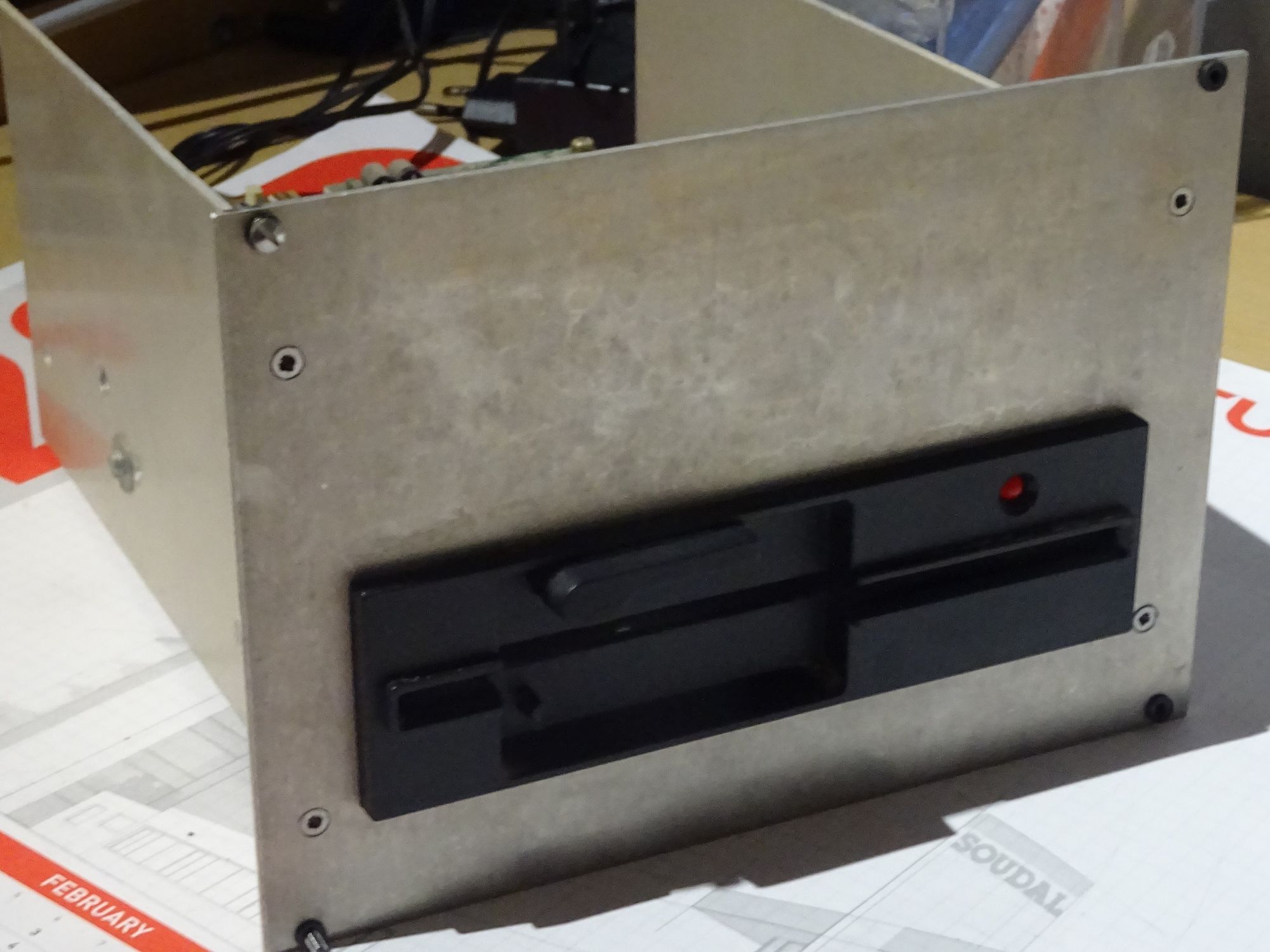
The system has both a 5.25’ drive and a 3.5’ drive. Both drives are standard PC floppy drives connected using the typical flat cables.
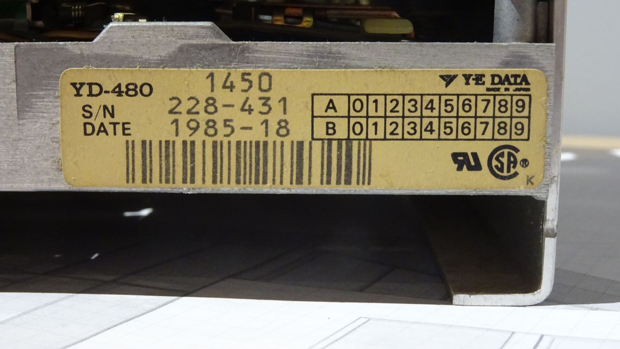
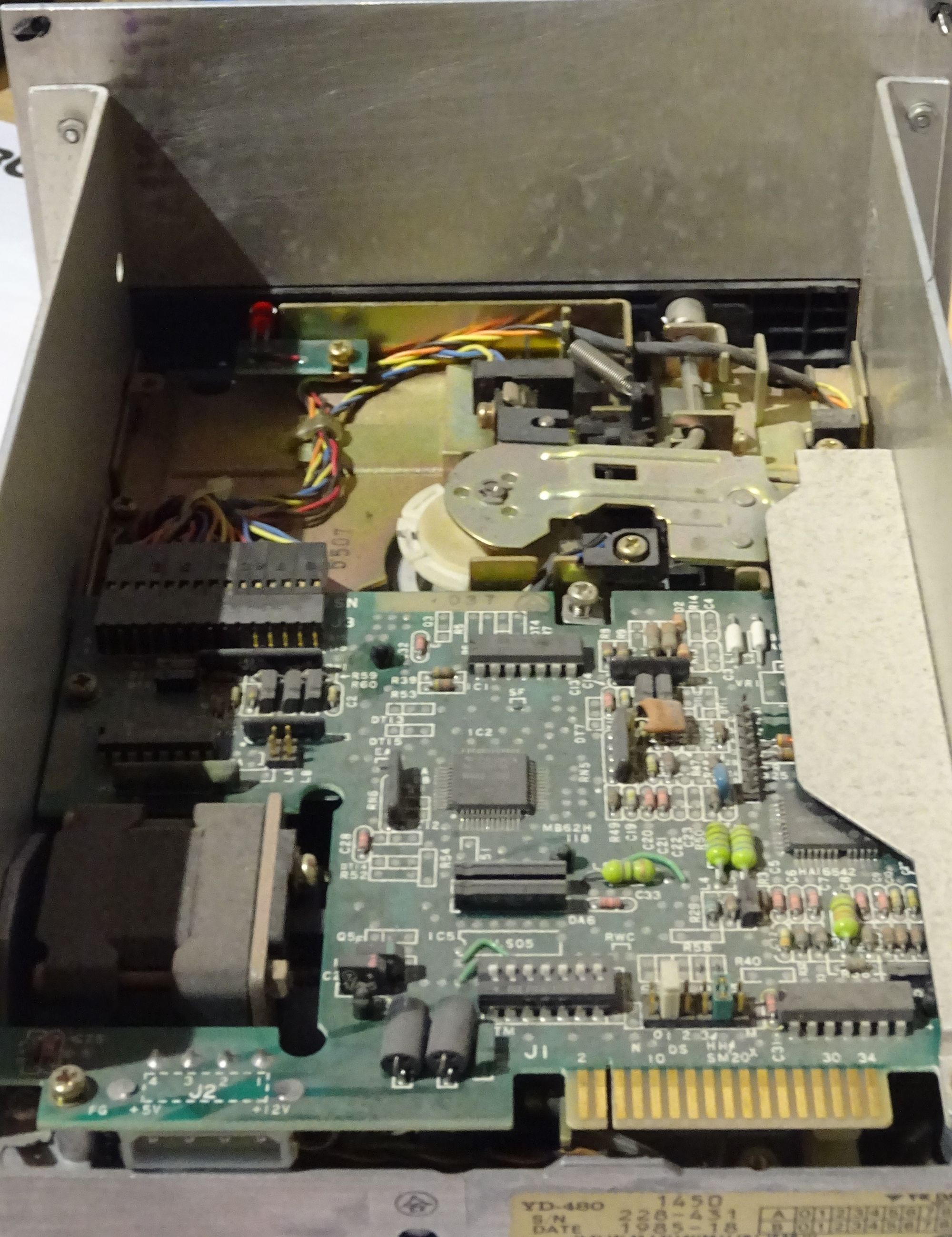
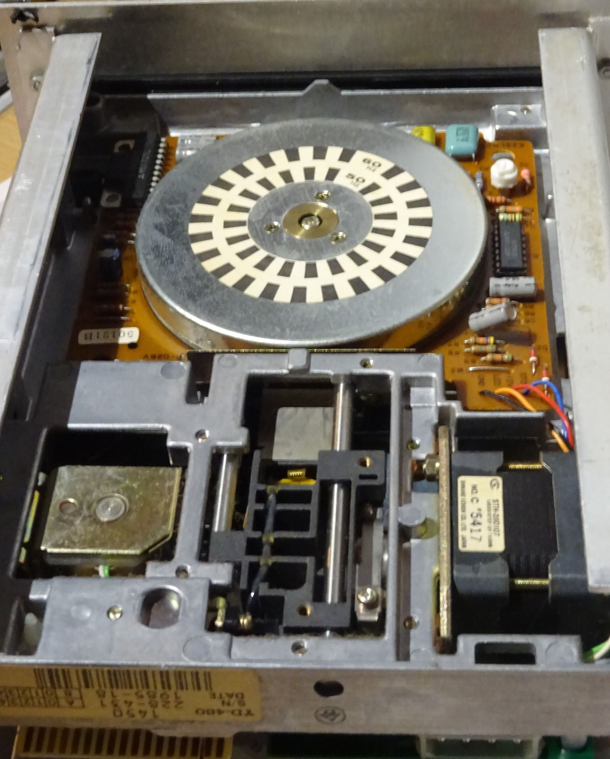
The 5.25’ drive is made by YE DATA. It’s model number is YD-480. It was empty when I got the unit.
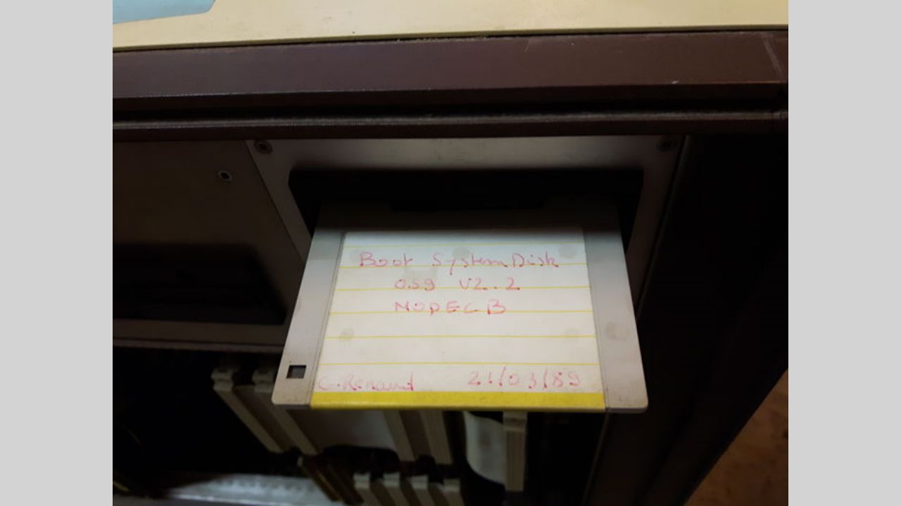
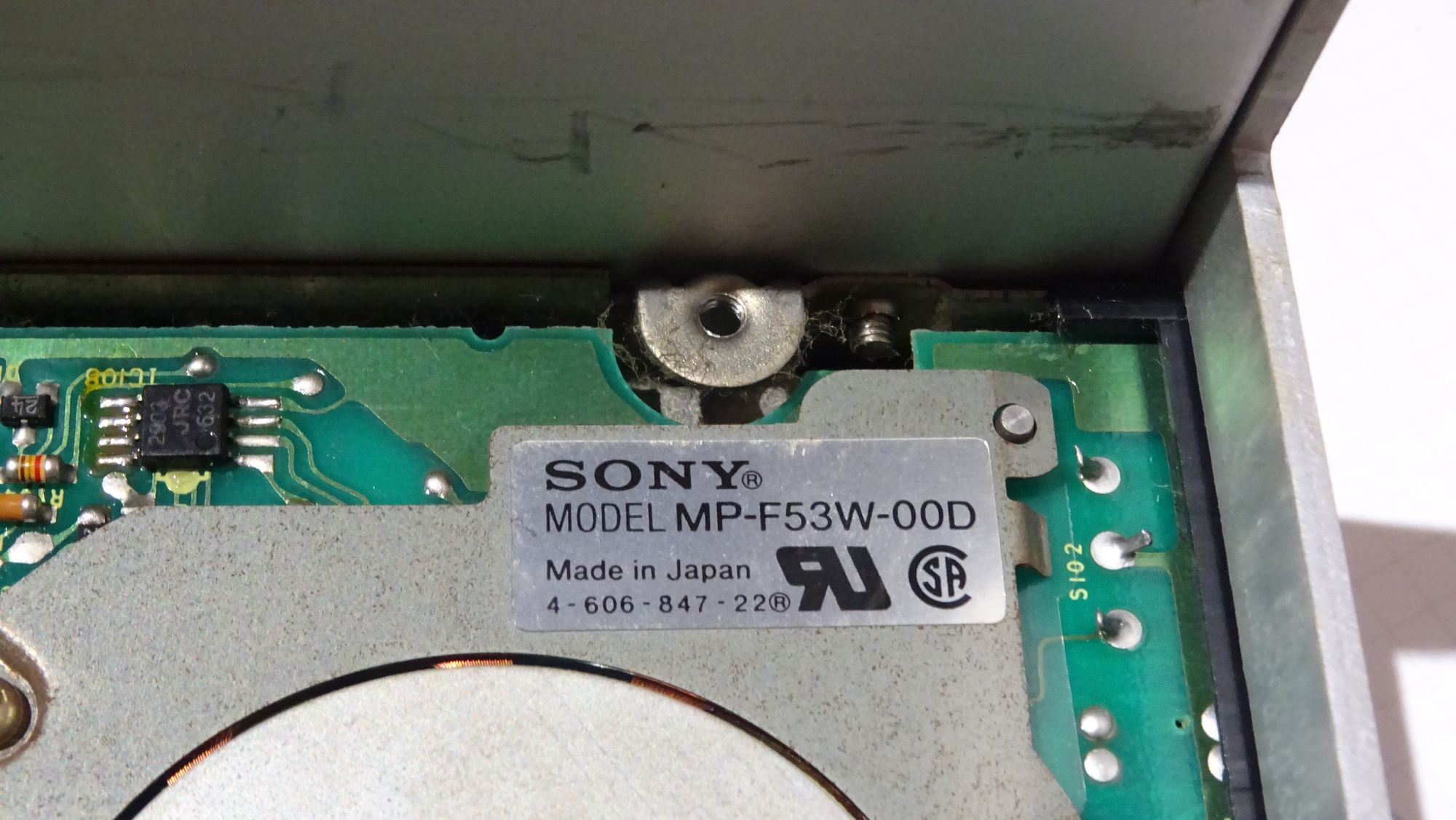
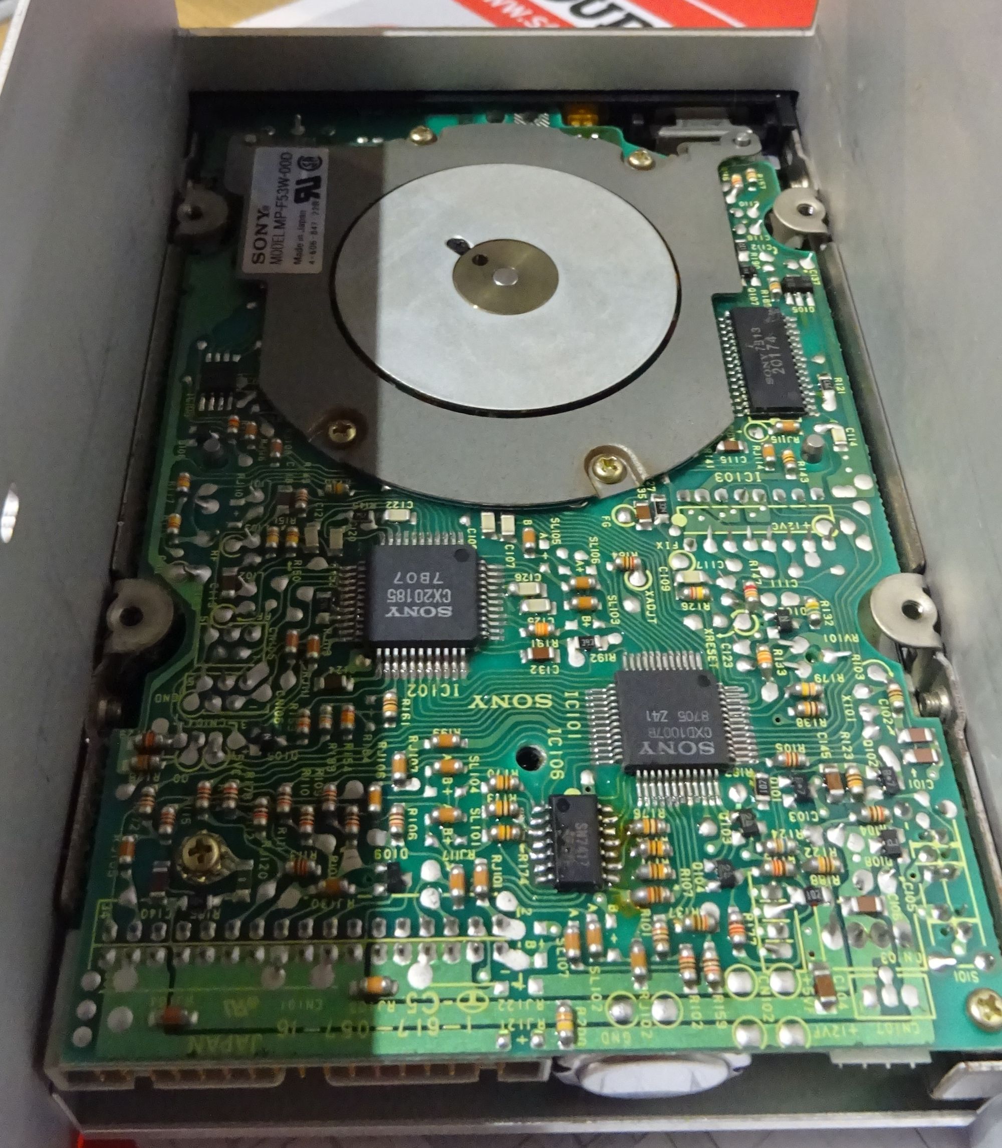
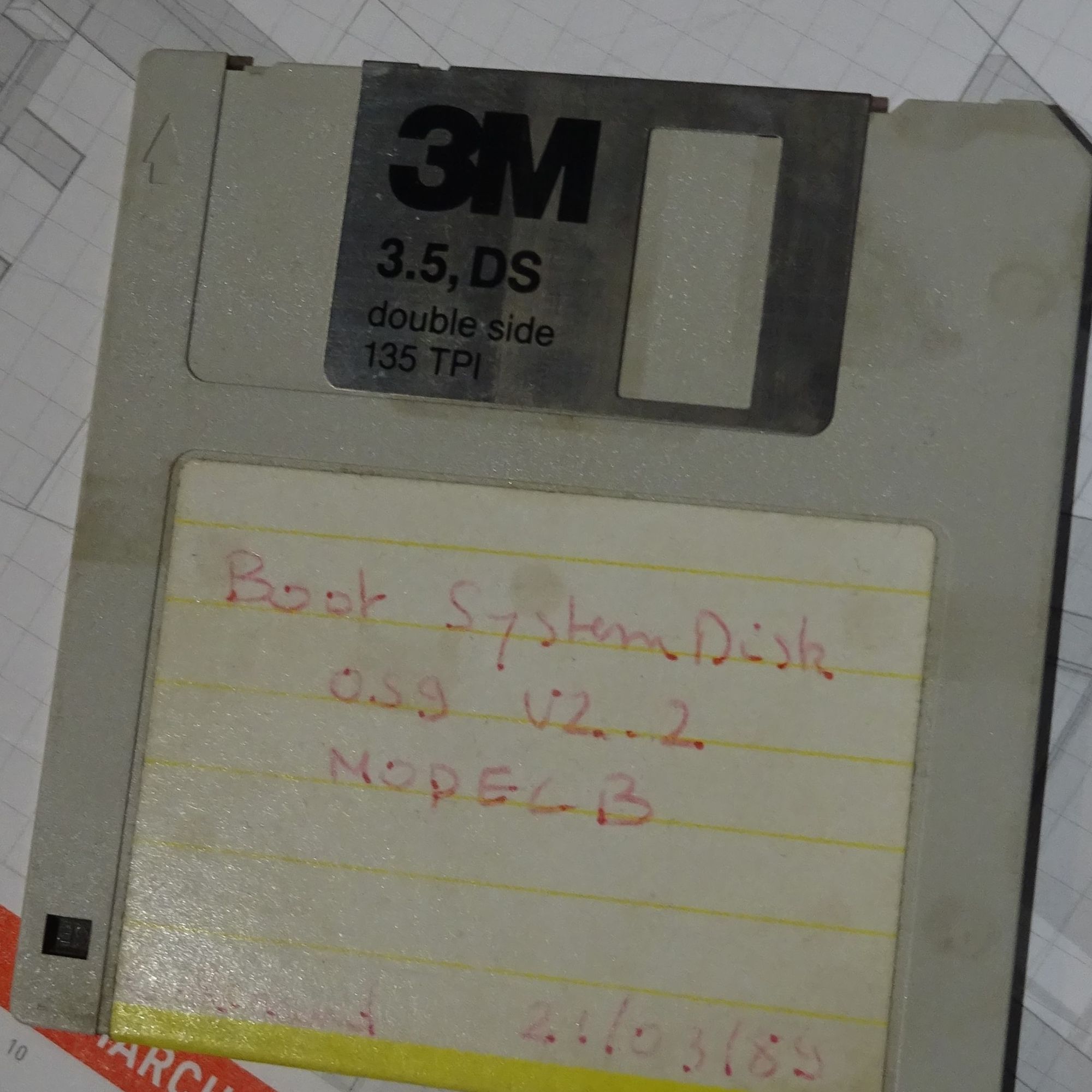
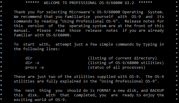
The 3.5’ drive is made by Sony. It’s model number is MP-F53W-00D. Inside this drive was a disk labelled “Boot System Disk OS9 V2.2 Model B”. It also has a date of 21/03/1989.
I wanted to preserve the data on this disk. In order to do this, I built a device known as a Greaseweazle, which is a DIY alternative to devices like the Kryoflux. This device is capable of making very accurate backups of disks on a magnetic level.
I made several backups, some more successful than others. Most of the data seems to be intact, which was a pleasant surprise given how poorly the unit was stored.
These backups are now available on archive.org along with some more info on how to work with the images.
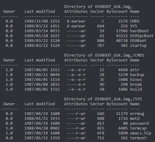
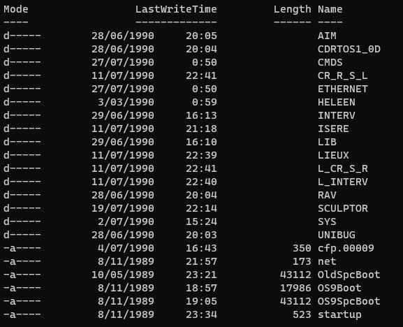
Looking at the contents of the floppy, there doesn’t seem to be much of interest. This is likely a generic OS9 boot disk with minimal or no modifications. CD-i Fan provided a listing of all files and directories. He mentioned that the OS9SCP file on the root of the disk contains a kernel as well as drivers for the floppy drives, hard drive, and serial. This is also the most recent file on the disk, dating from 1989. Most other files date back to 1987.
Hard drive
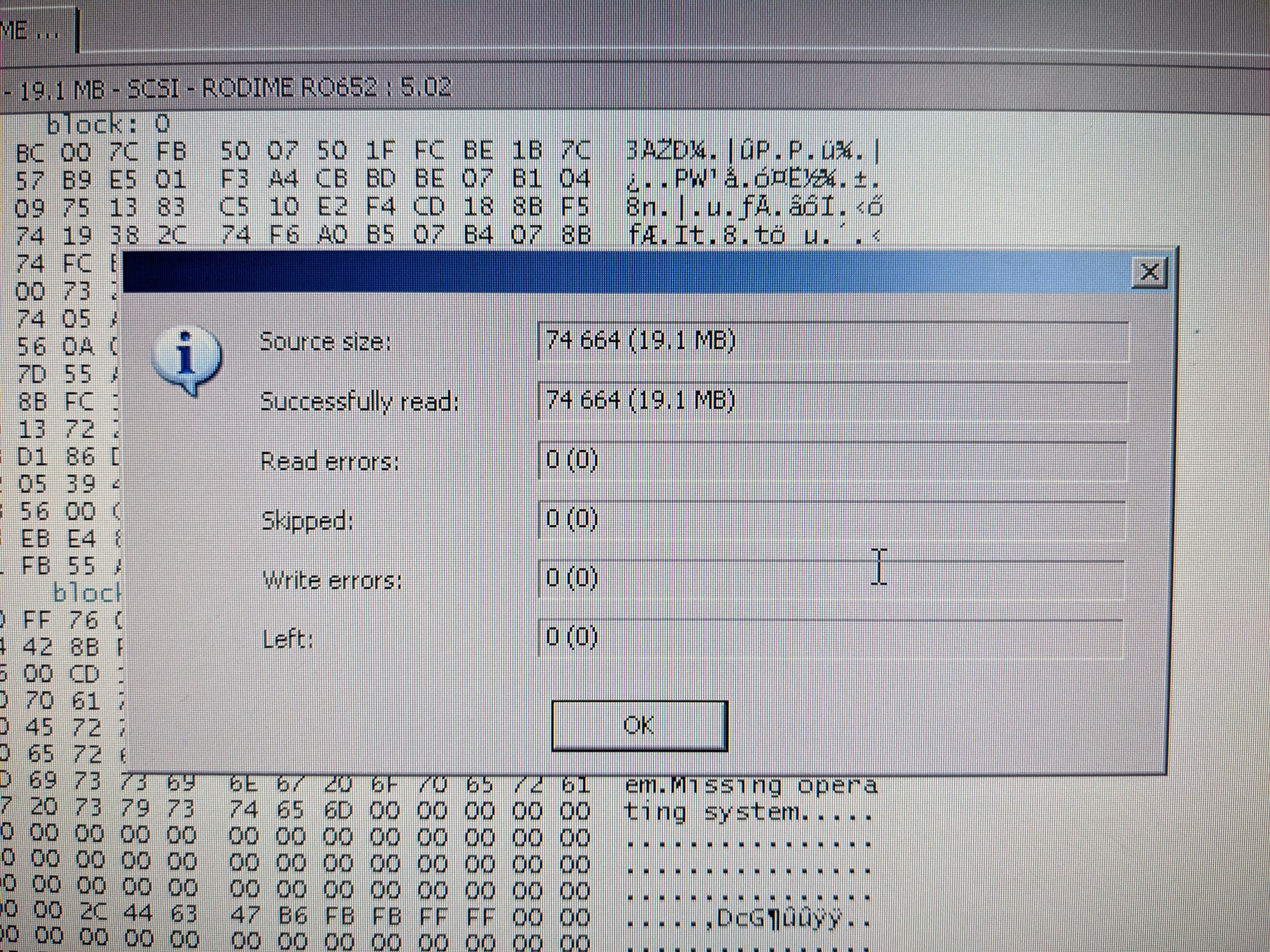
The HDD in the system is a RODIME RO652. It’s a SCSI drive, similar to what you would find in external drive enclosures for 68K Macintosh systems at the time. It has a capacity of 20MB.
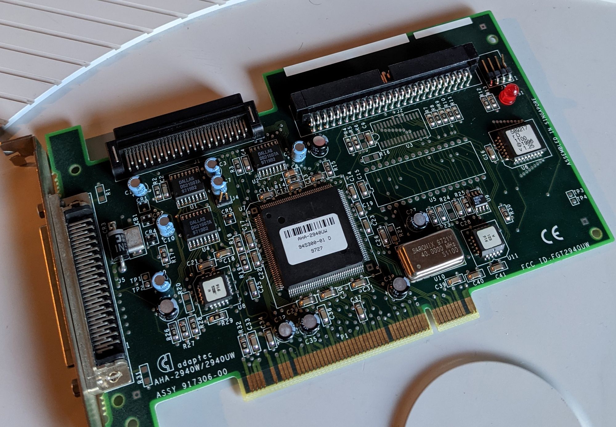
Just like with the boot floppy, I wanted to safely preserve the data on the disk. I ended up doing this using a Pentium III PC running Windows XP. The PC had an ADAPTEC AHA-2940UW SCSI card installed which seemed suitable for the job. The software I used to make the backup was DMDE.
Update: It should be emphasised that this method should NOT be used when preserving writable media. Sadly, I did not realise this sooner. Windows will automatically overwrite the boot sector of writable media if it can't recognise the filesystem. Always use Linux for this kind of backup. I did use several Linux live CDs to attempt imaging the drive in a safer way, but was unsuccessful for unknown reasons, possibly due to its non-standard command set. Individuals involved with preservation-oriented emulation projects, MAME in particular, can often point an individual towards knowledgeable people. If all else fails and Windows really is the only option, please look into after-market devices available which can block write commands across various interfaces.
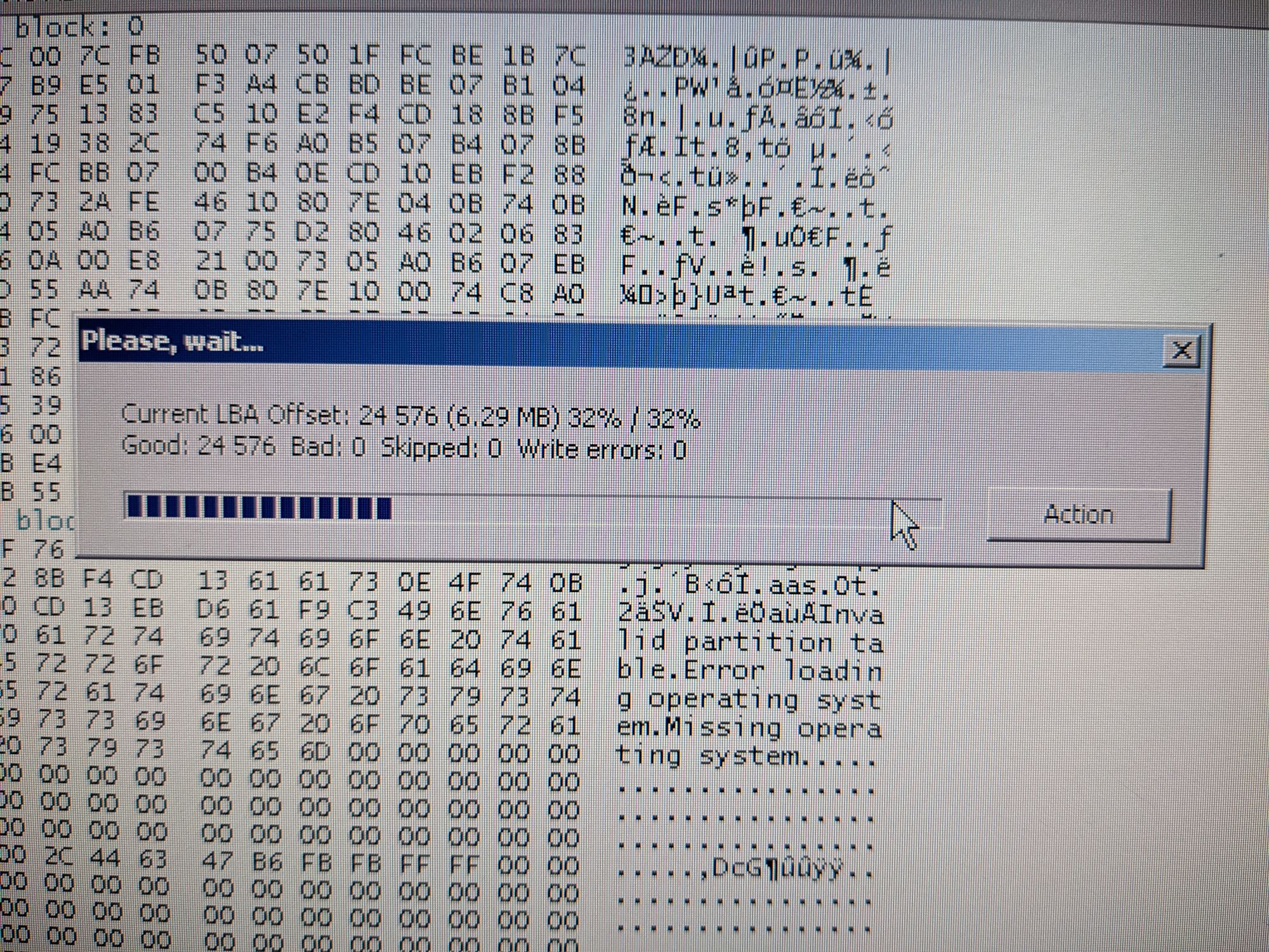
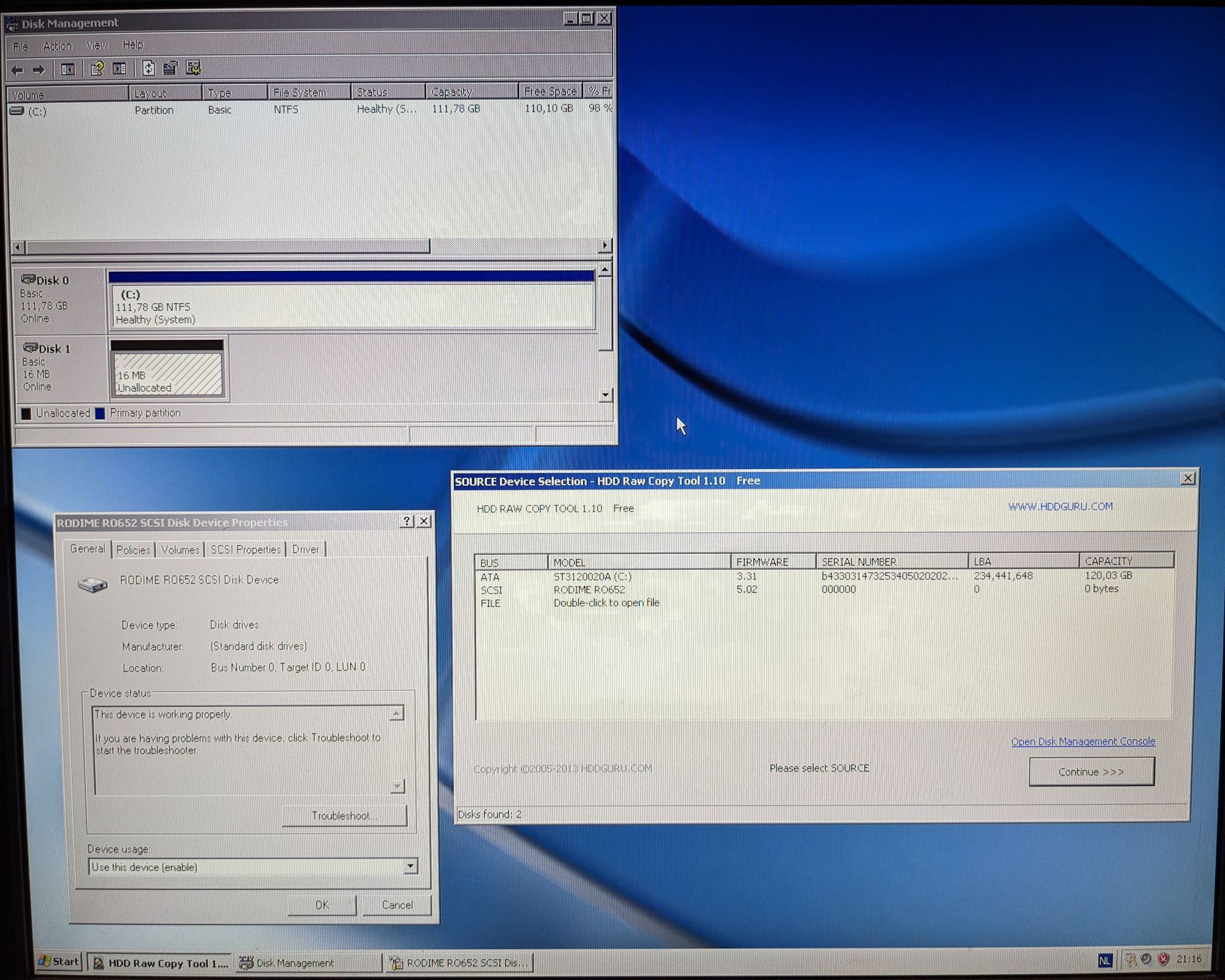
The backup was successful, with all the data intact, except for one part: the boot sector. It’s almost certain that Windows modified this sector. Luckily, the rest of the data was untouched. When it comes to handling the HDD image, I once again have to give a massive thank you to CD-i fan. Not only did he extract the data from the image in a format that’s readable on modern PC’s, he also managed to restore the boot sector of the image, undoing any damage done by Windows.
I won’t be going over every single file on the drive, as that would make the page even longer than it already is. I will point out the things of interest that are relevant to this machine/the CD-i. If you would like to explore the full contents of the drive, feel free to do so by downloading the backup at the bottom of the page.
All files on the HDD were created between late-1989 and mid-1990. This is after the CD-i’s hardware and software was finalised. This, along with the fact that there’s seemingly no files on the HDD relating to the prototype video boards, makes it clear that the HDD was at some point erased. This is unfortunate, as that means we don’t have any software for the video boards. By looking at the files and software currently on the drive, we can assume this machine was at some point repurposed as a generic OS-9 development unit used for developing various CD-i applications.
Some of the interesting things currently on the drive:
- A folder named ‘CDRTOS1_0D’ containing an early build of the CD-i’s OS. The first finished CD-i player, the CD-i 180, came with CD-RTOS 1.1.
- Generic OS9 system files and drivers.
- Various folders with random test data like names of people, places, etc.
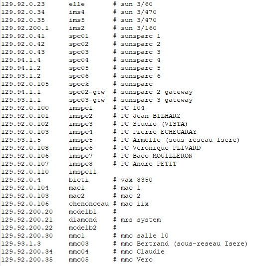
- A hosts file containing names of other machines in the network, including SUN workstations typically used in CD-i development. This also confirms that this machine was very likely connected to a network at one point. Nothing very useful about this, but it is neat to see.
- An application named ‘sculptor’, which seems to be a DBMS (database software) of sorts. Hence the large amounts of random test data on the drive.
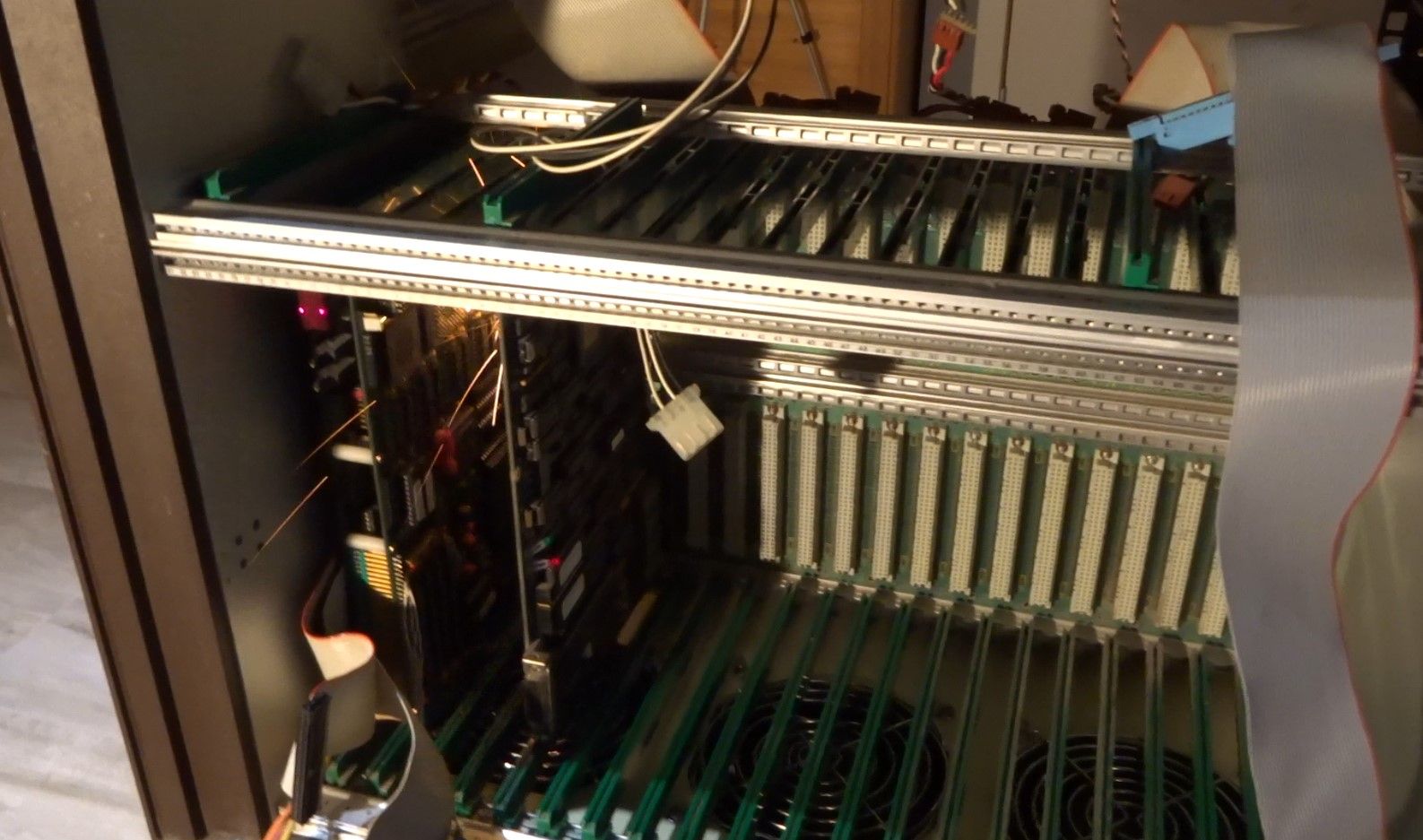
VME boards
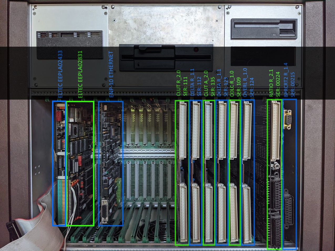
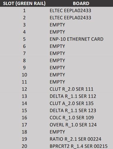
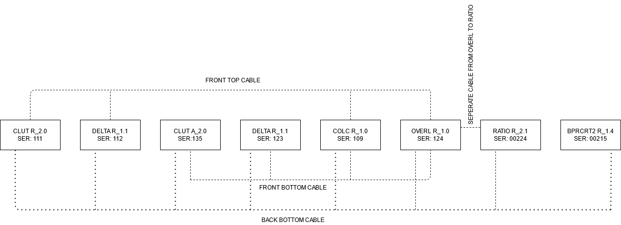
The system has a number of VME boards that together form a full computer. It is important that all the boards are installed in the correct position, and correctly connected to each other using flat cables.
I created the following visuals to document what order the boards should be installed in, and how they should be interconnected.
CPU board and network card
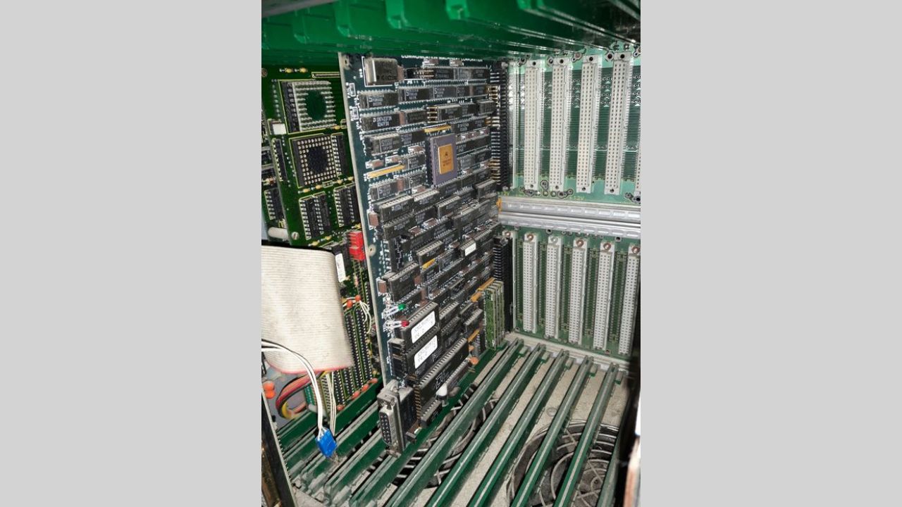
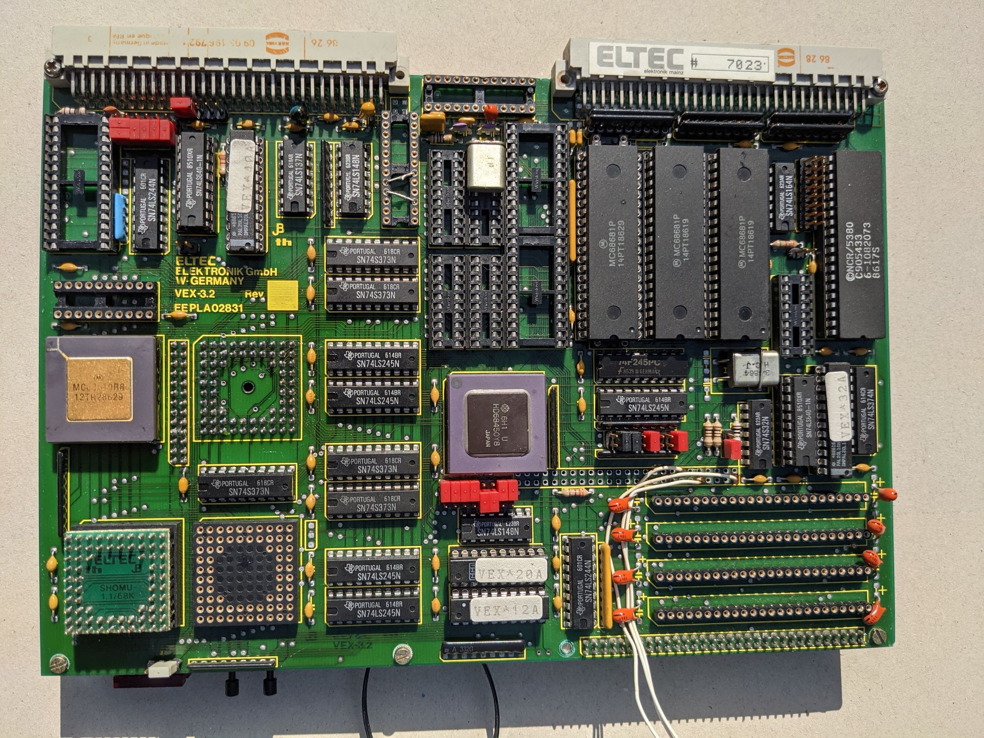
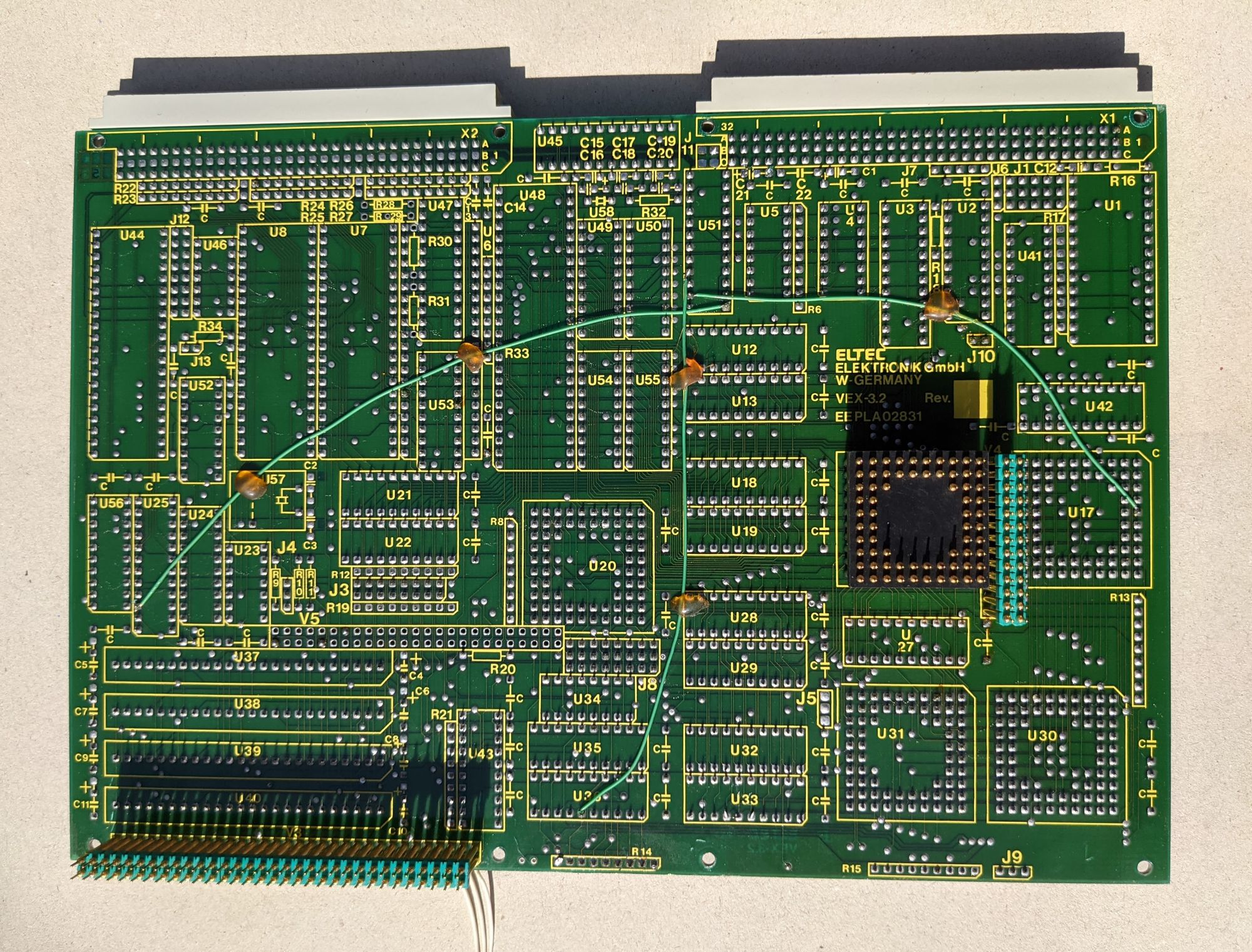
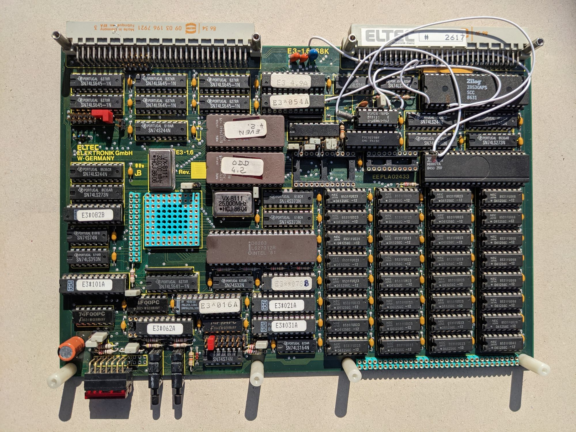
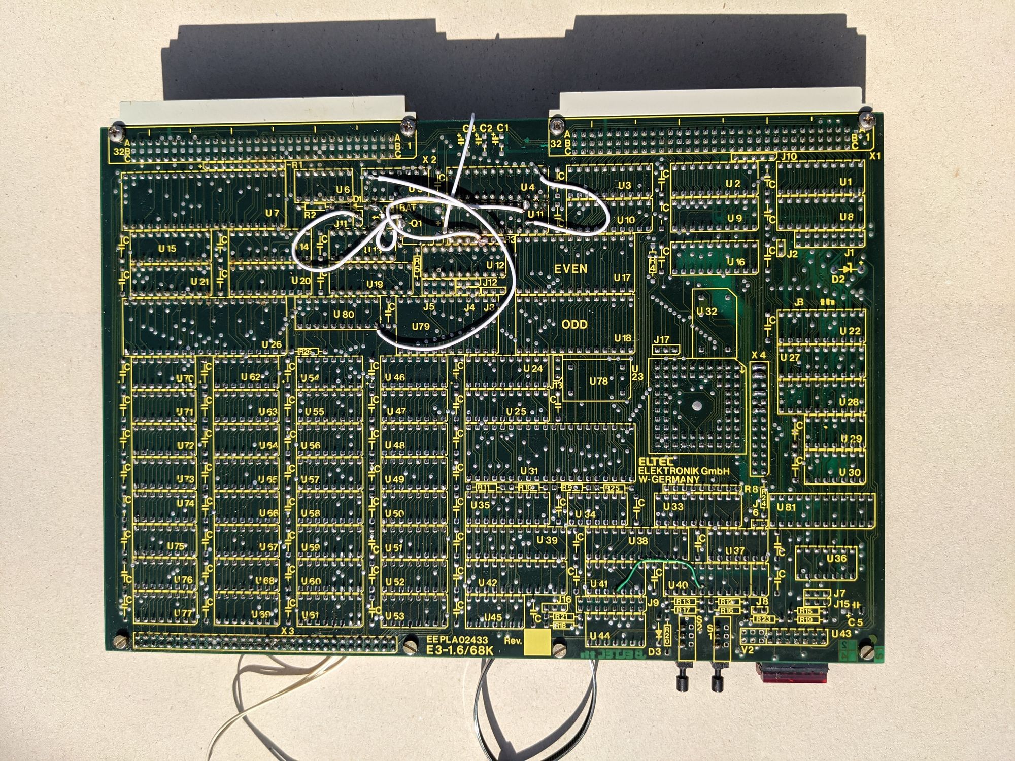
The main CPU board is made by the German company ELTEC. It consists of 2 PCB’s stacked on top of each other and connected using metal pins and sockets.
Here’s the noteworthy things found on these PCB’s:
- A Motorola 68010 CPU
- A HD68450Y8 DMA controller
- 32 NEC D41256C-12 RAM chips, with a capacity of 256kb each, making for about 8mb total
- An Intel D8203 DRAM controller
- Two buttons, both are unlabelled but by looking at many other similar VME boards, we can assume they are ‘reset’ and ‘pause/halt’
- A hexadecimal display, presumably used for displaying the status of the board
- A Zilog SCC Z8530APS for serial communication
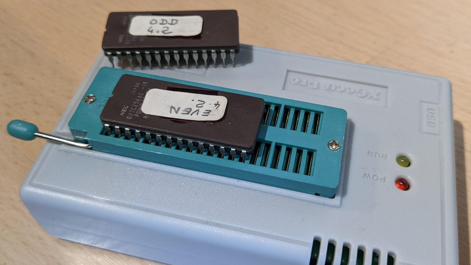
- A MB8877A floppy controller
- Two NEC ROM chips containing the kernel for the board
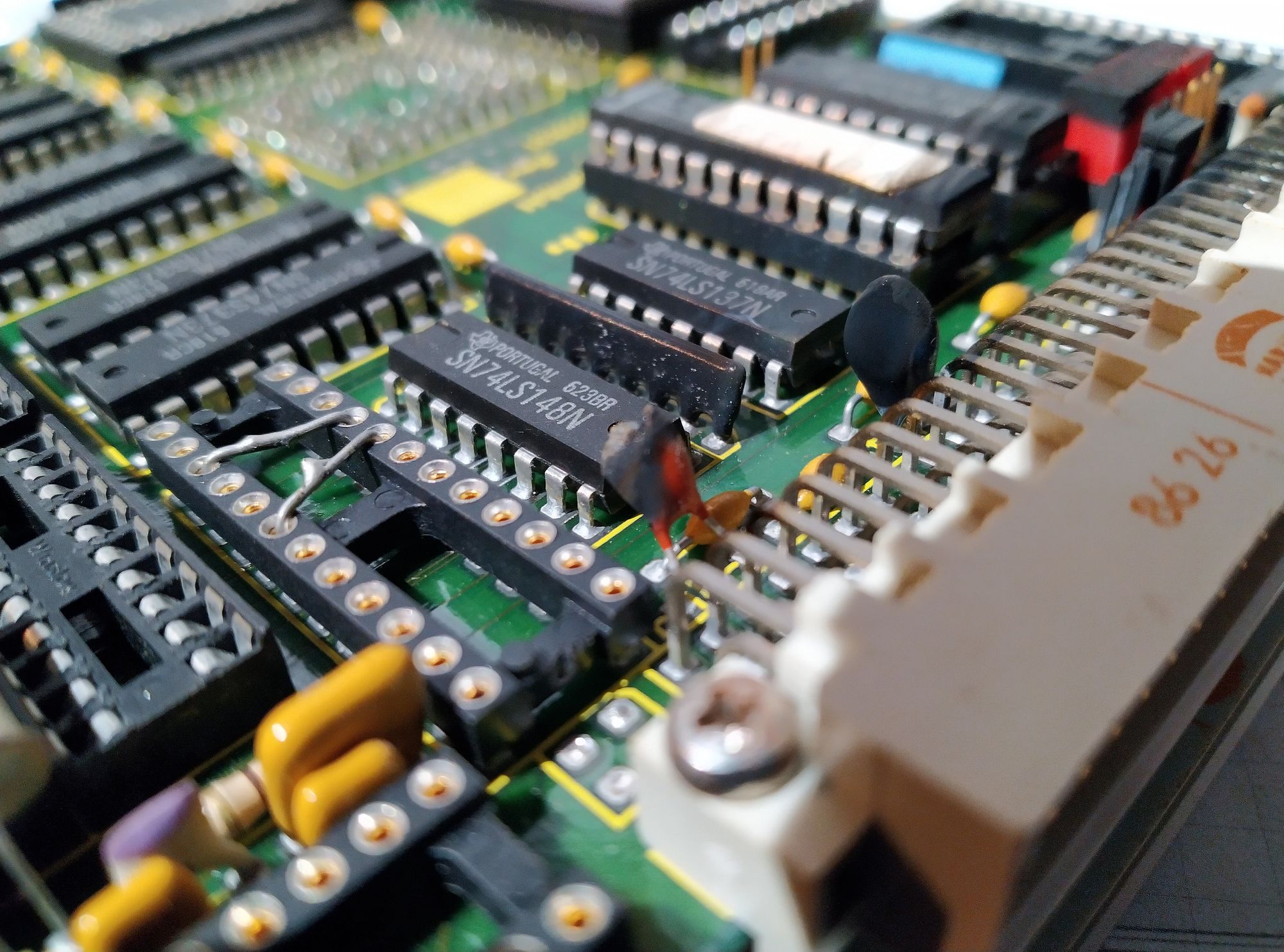
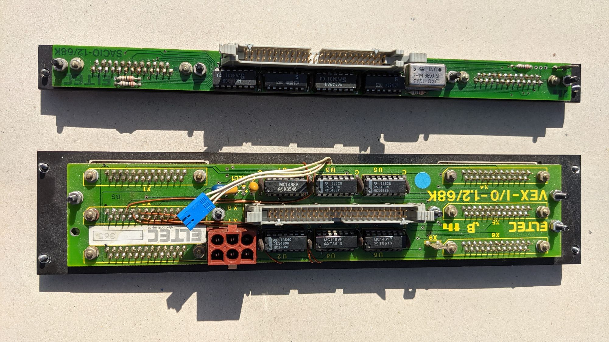
The HDD and floppy drives are connected to this board in the back of the system. Two flat cables run from the back of the backplane to the front of the system for connecting two brackets with serial ports to the CPU board(s). One of those brackets also has an additional power plug as well as a small wire that connects directly to the CPU board. It looks similar to the connectors for modern PC fans.
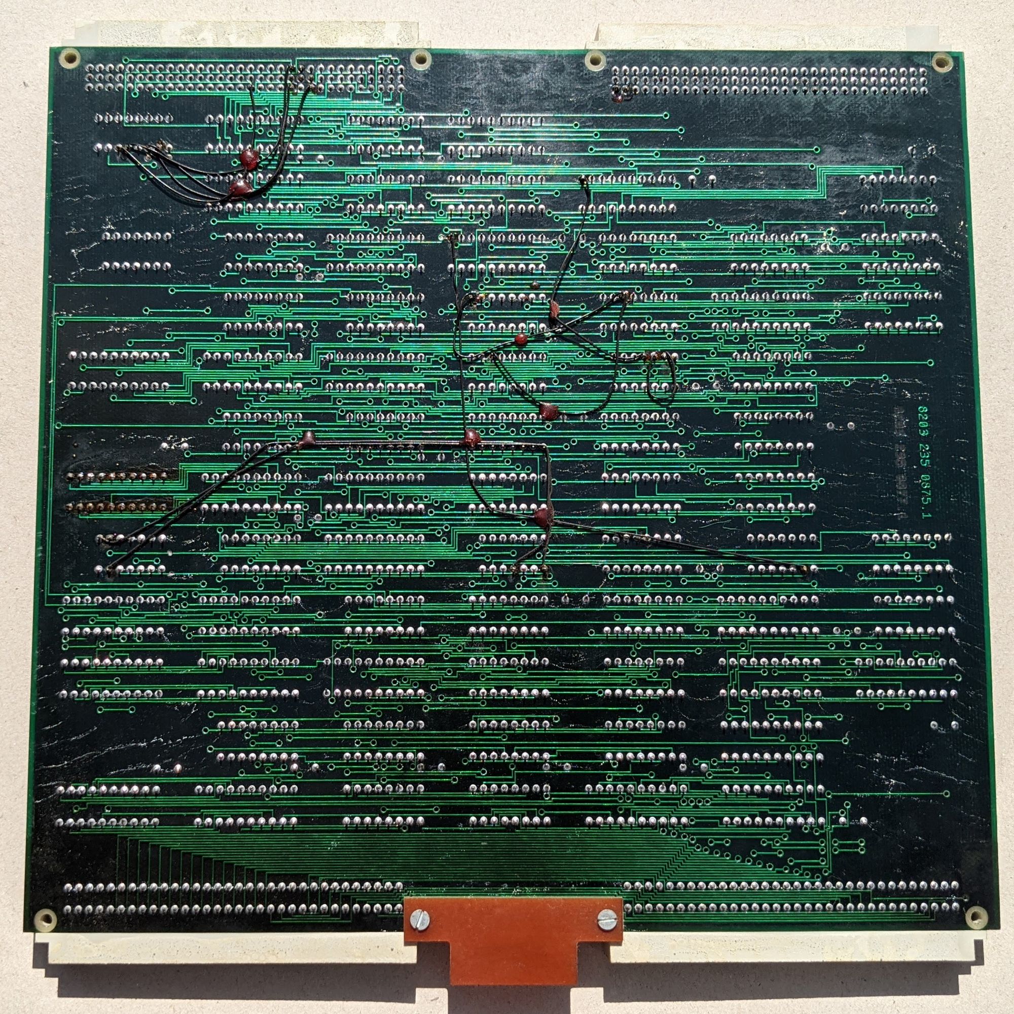
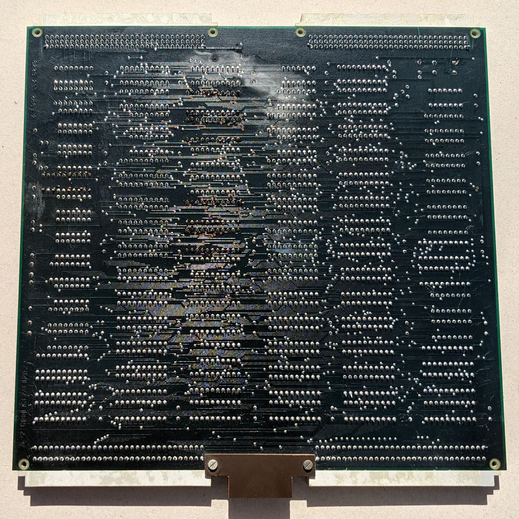
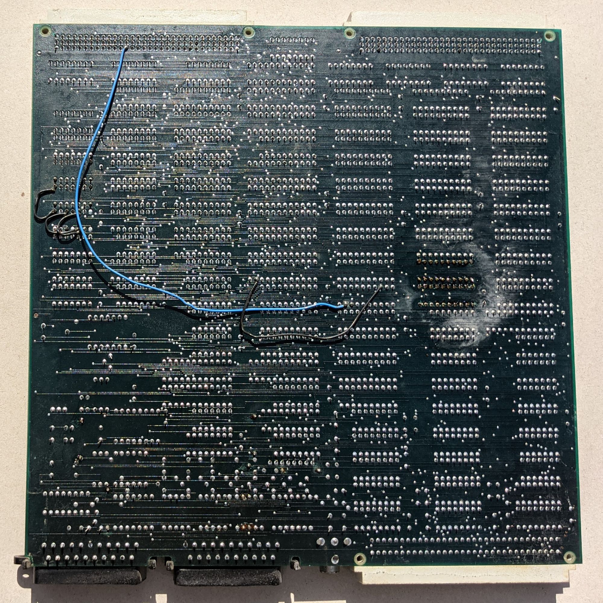
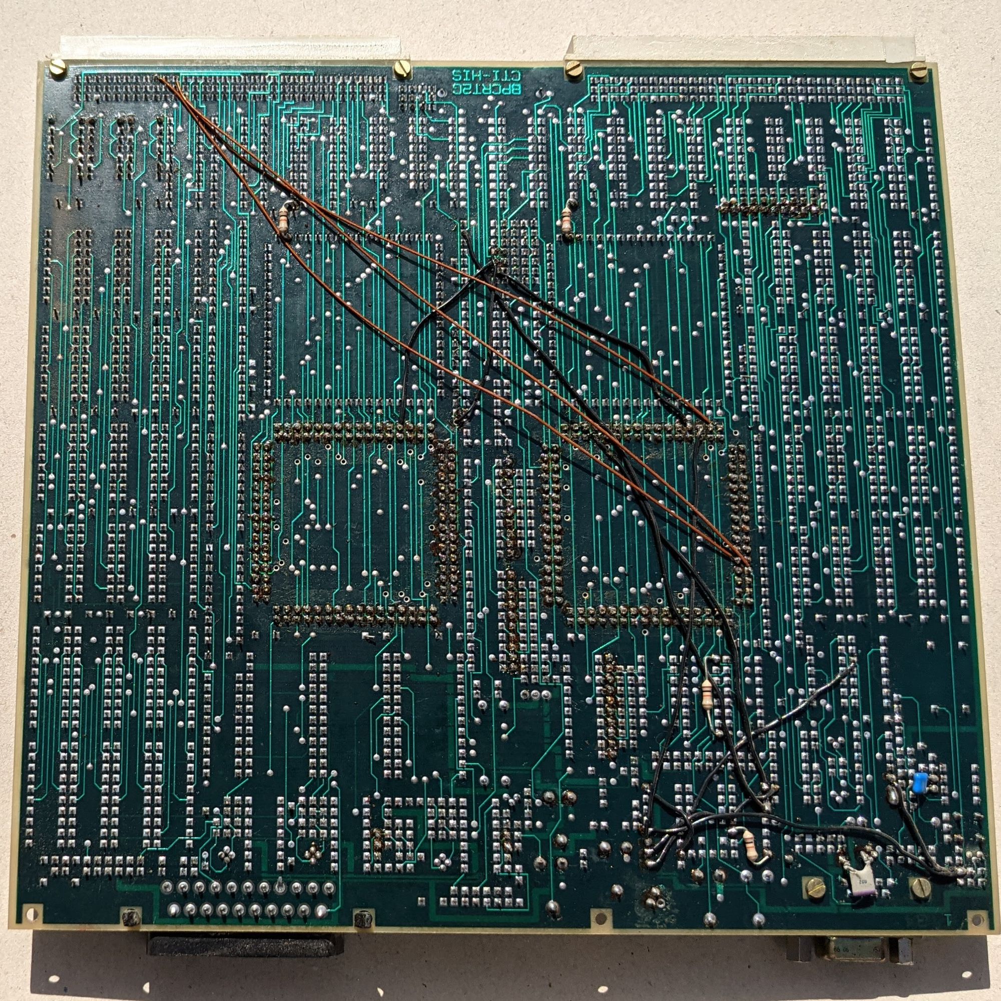
The white bridge wires in the following images are my doing, the green wires on the bottom were already there when I got the machine.
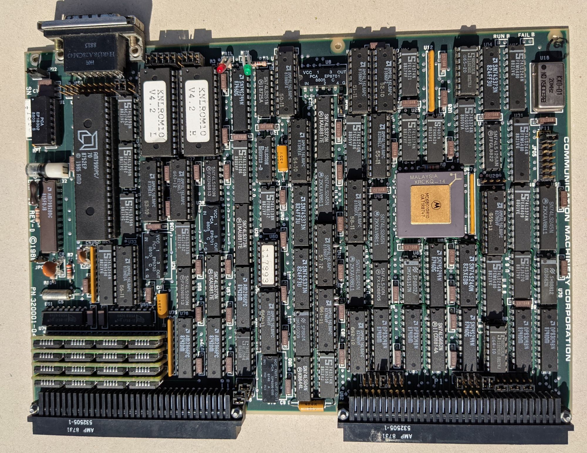
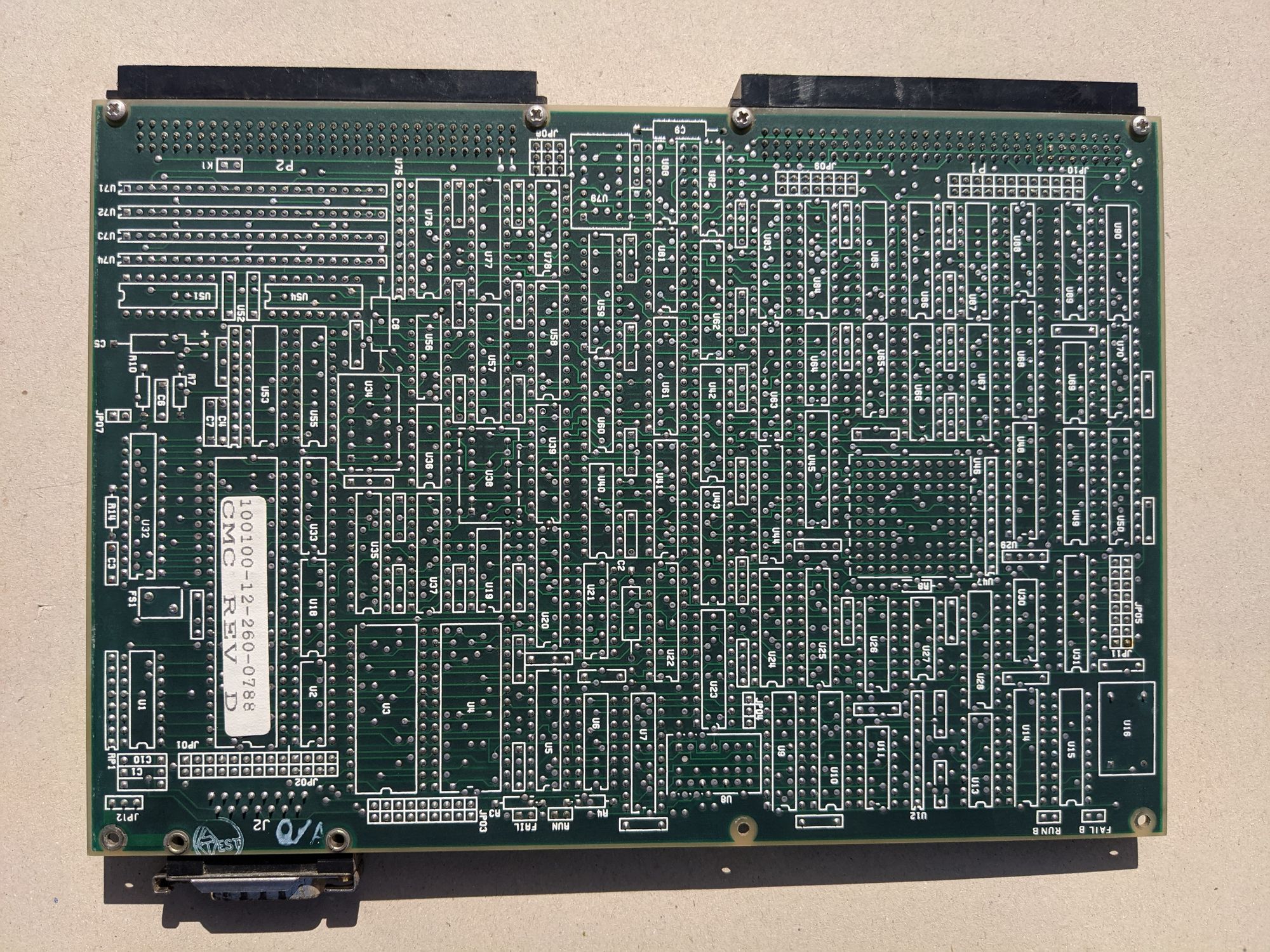
Next to the ELTEC boards is an ENP-10 ethernet card by Communication Machinery Corporation. This is a standard VME ethernet card design. It has it’s own ROM chips, it’s own RAM, and even it’s own 68010 CPU, presumably used for TCP-IP functionality. The card also has two LED’s labelled ‘RUN’ and ‘FAIL’. When the system is powered on, the FAIL LED lights up, but after a few seconds, it turns off and the RUN LED turns on. This indicates that the ethernet card is very likely working fine.
Unfortunately, the CPU board is most likely the reason the system doesn’t POST/boot. As mentioned before, it had a typical ‘barrel’ battery that had started leaking probably a long time ago. It has eaten away and corroded many traces, sockets, and other nearby components. Despite my best efforts to clean everything and create bridges for the broken traces, I could not get the board to work. It’s likely the board will need to be fully replaced for the system to work again. Luckily, it is a standard design, but it seems to be very rare.
Even though the CPU board wasn’t booting, I could still dump the kernel ROM using an EEPROM programmer. I did the same thing for the ROM chips on the ethernet card. Both dumps can be downloaded at the bottom of the page. These dumps allow emulation to be attempted, more on this in the next section.
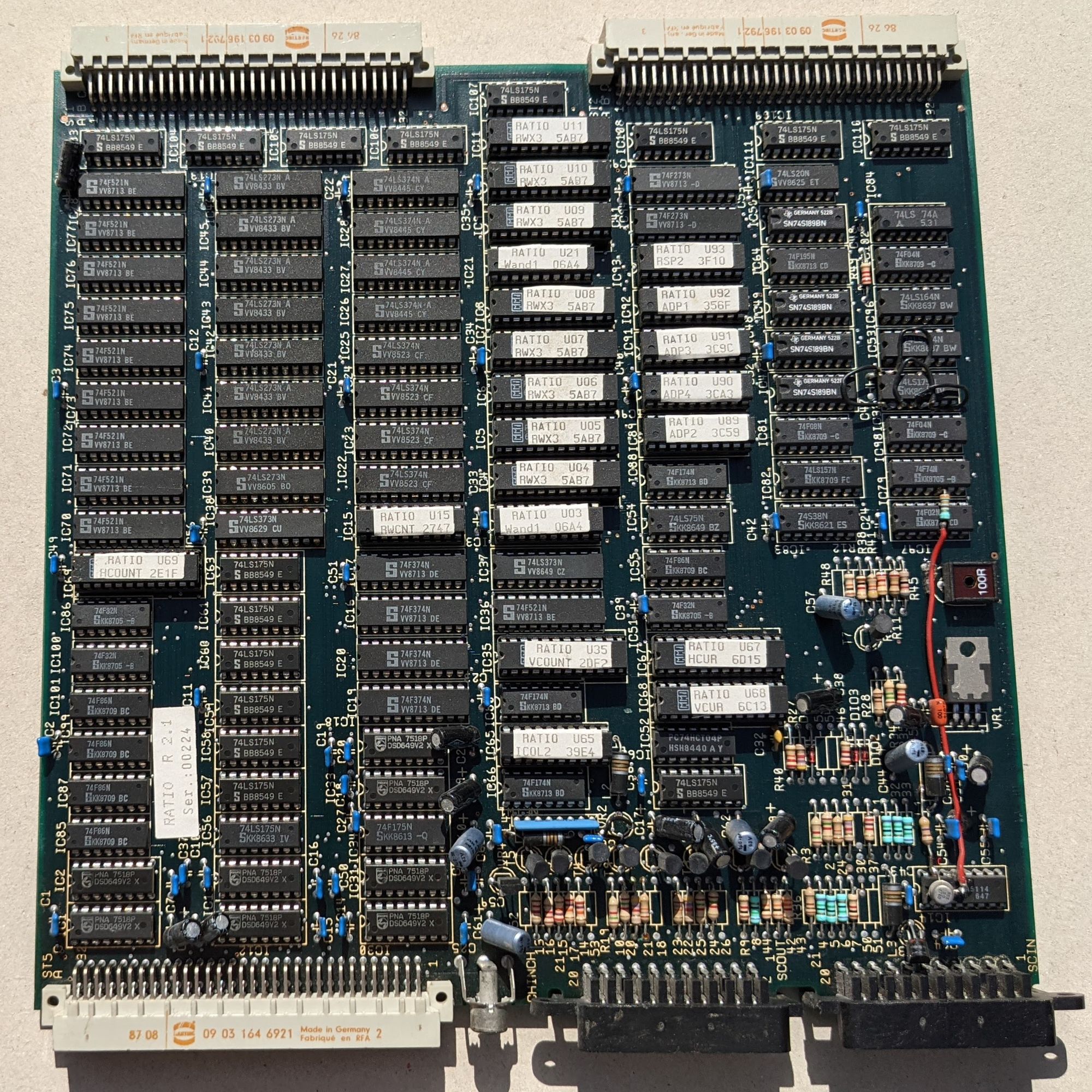
Video boards
As mentioned before, what makes this machine particularly interesting and unique are the video boards. There’s 8 in total, each serving a different role in the video circuit. You'll notice that the boards all have a number of on-the-fly fixes like jumper wires, bent pins, weirdly installed components, etc. None of this was done by me, this is what the boards were like when I first got the machine.
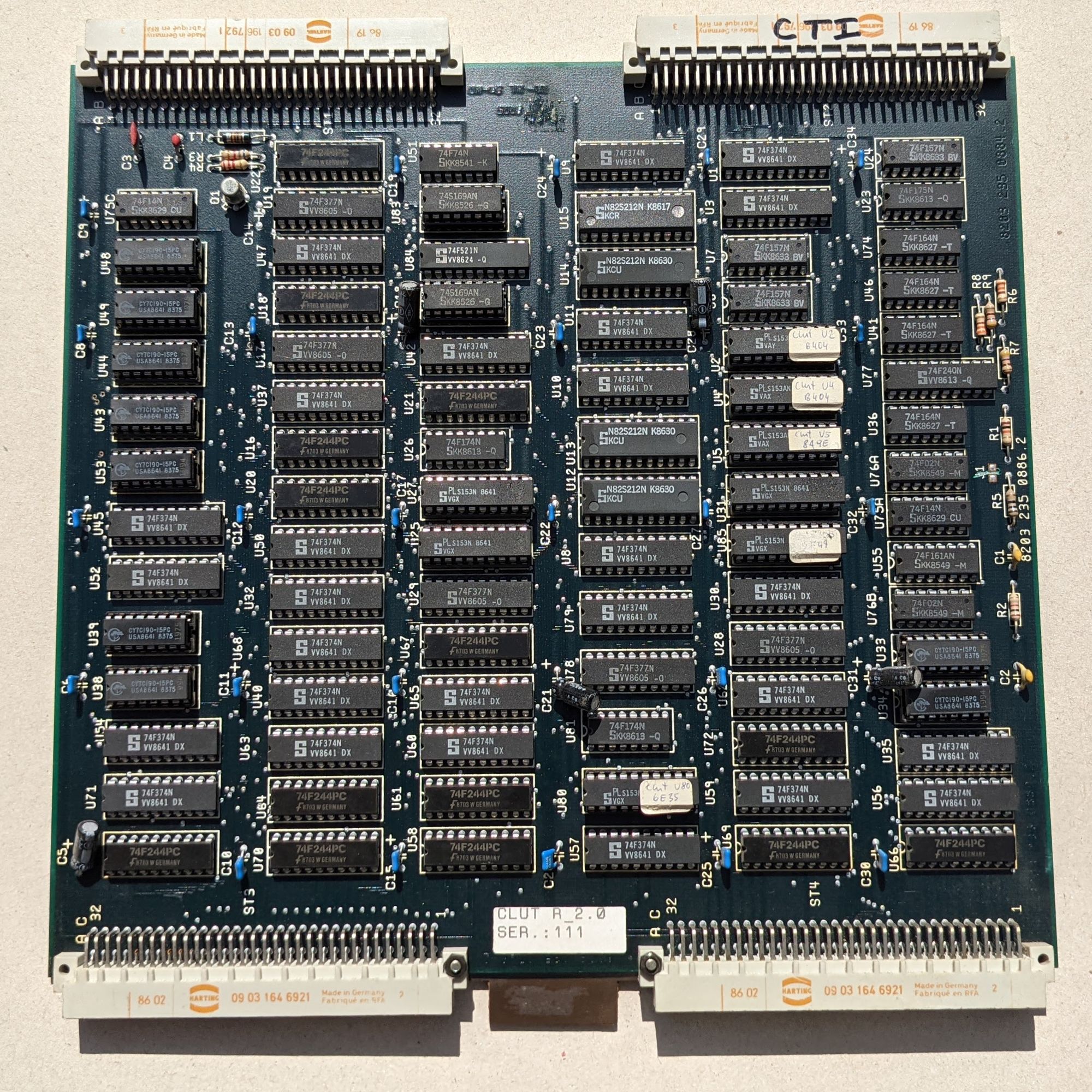
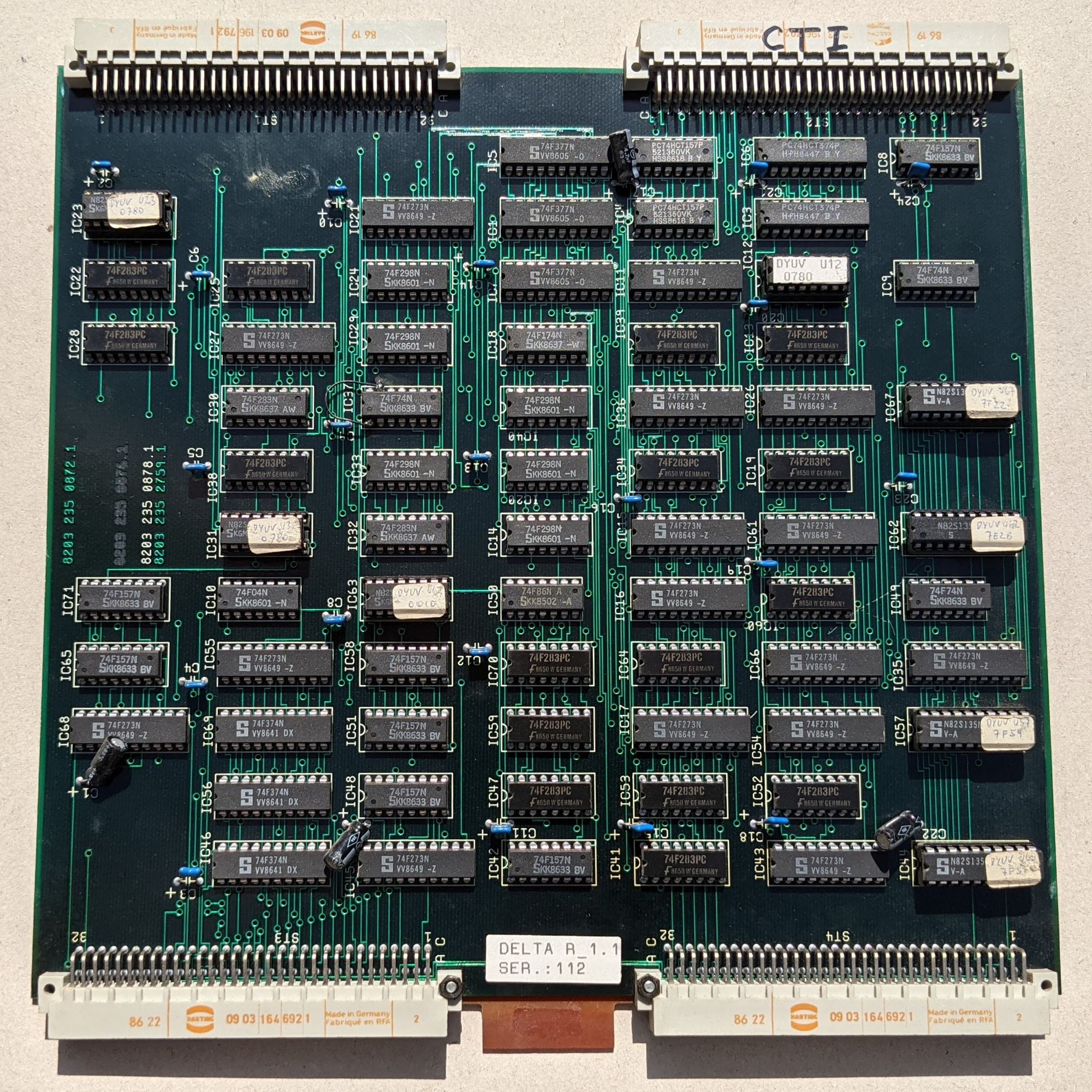
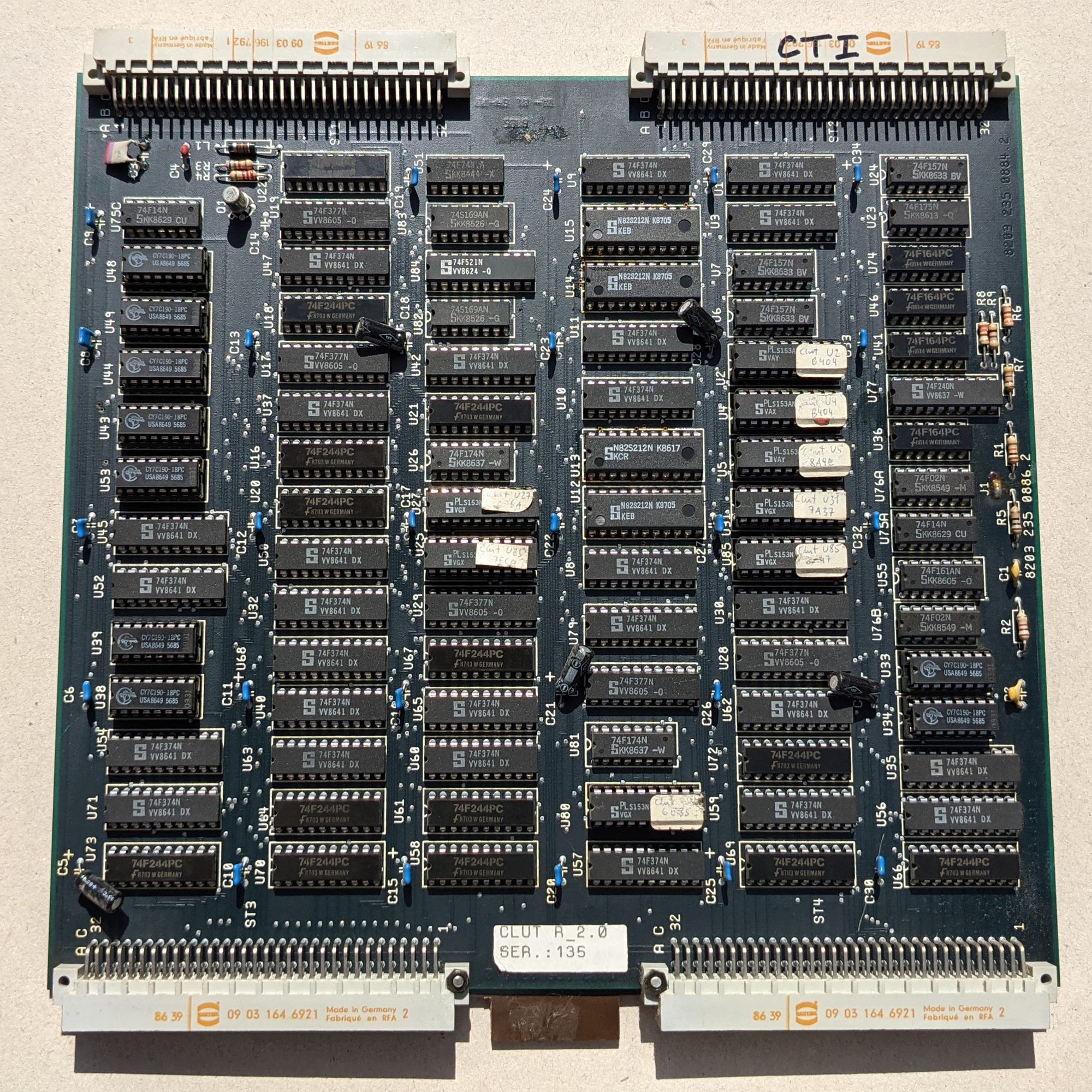
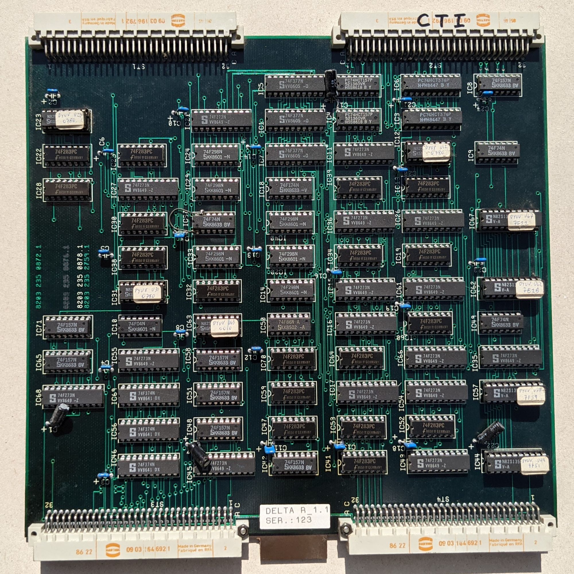
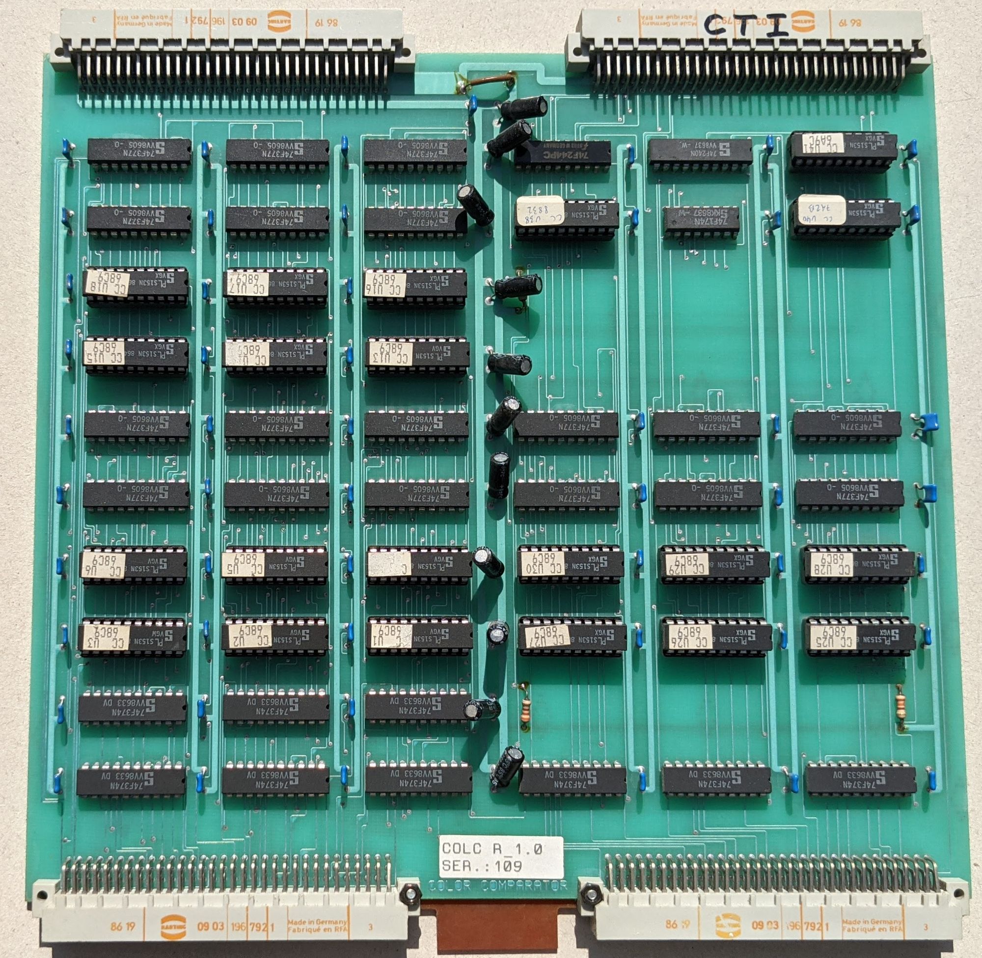
There are two boards labelled CLUT, which stands for Color Look Up Table. There’s also two boards labelled DELTA, which comes from Delta-YUV or DYUV. If you would like to know what both CLUT and DYUV mean in relation to the CD-i, please refer to ICDIA’s FAQ, which explains it much better than I ever could.
The reason for there being two of these CLUT and DELTA boards, is that the CD-i architecture includes 2 video planes that use CLUT and DYUV. In other words, there’s one board for each plane.

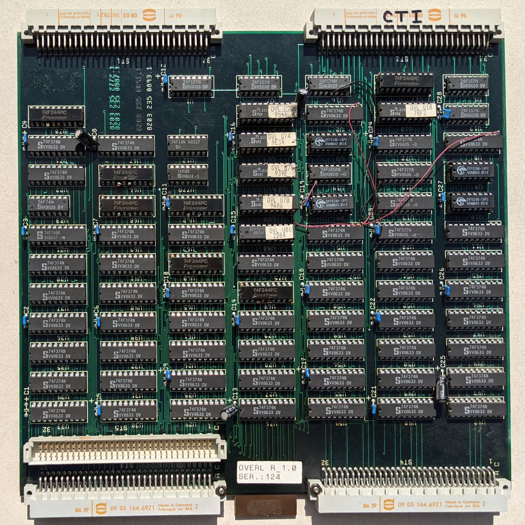
Next up is the COLC board, which stands for color comparator. This board works hand in hand with the OVERL board to form the overlay video plane. The OVERL board has one peculiar thing: an extra VME connector in addition to the usual 4. This connector is used to connect the OVERL board directly to the RATIO board.
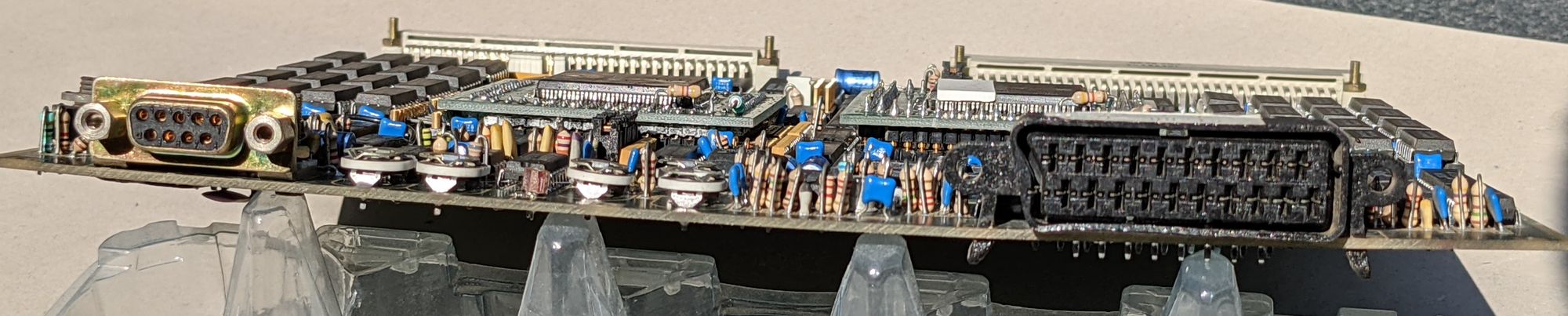
The next board is the RATIO board, which generates the actual video signals. It has 2 SCART sockets and one RCA connector.
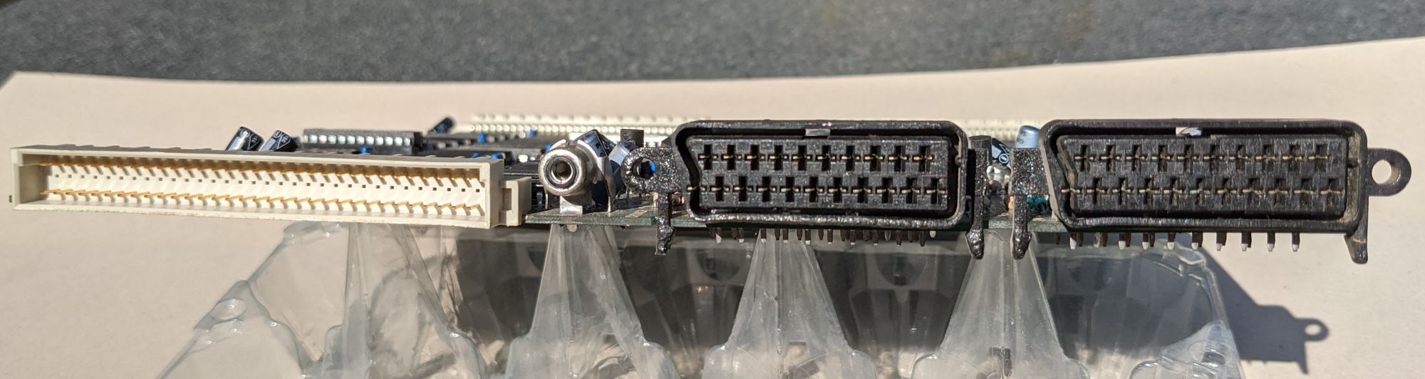
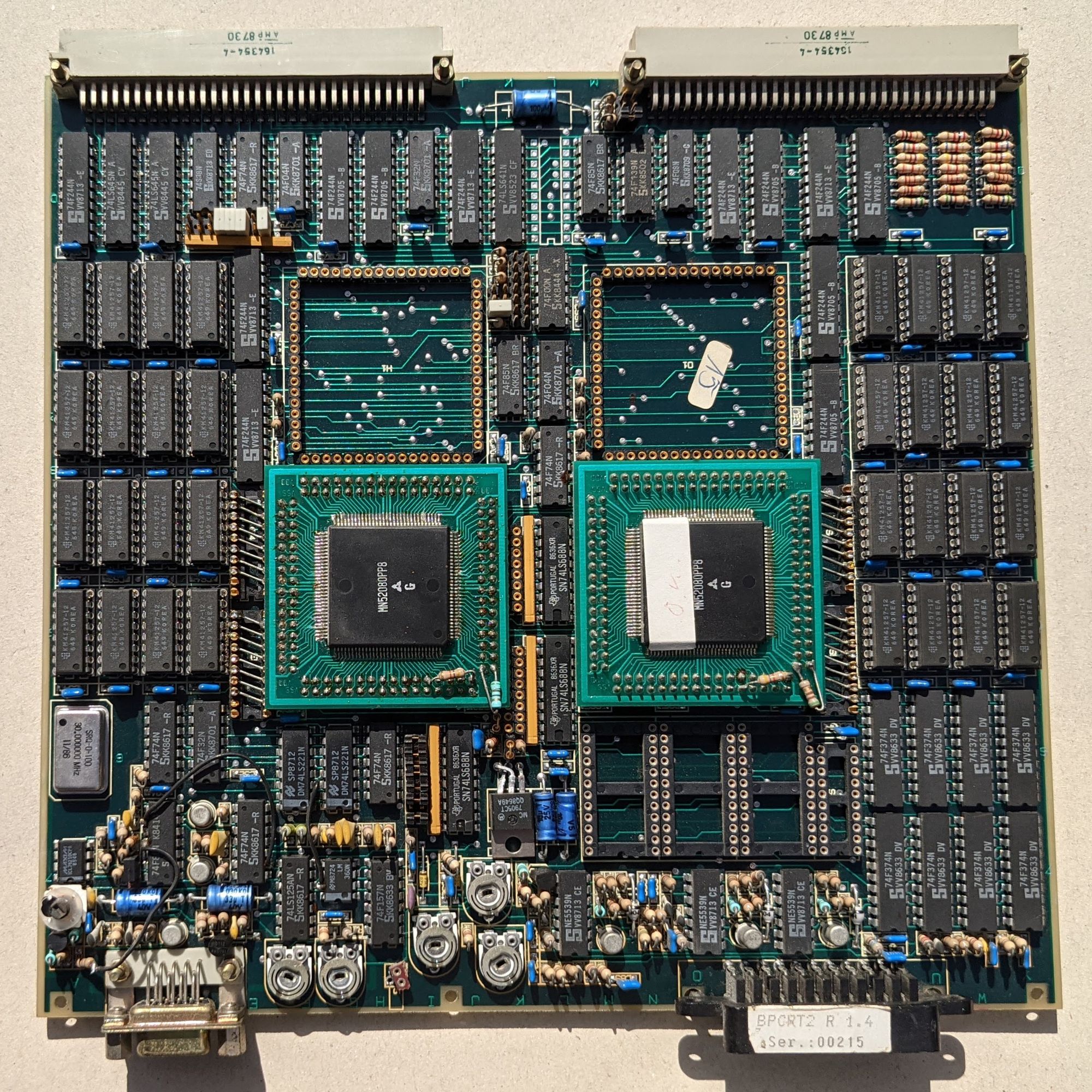
The final video board is the most mysterious of them all. It’s labelled BPCRT2. What this means is not known for sure but ‘Board Prototype’ CRT could be a possibility. The board has one SCART socket and a DB9 connector. There’s 4 large square sockets on this board. Two of those sockets have a Matsushita MN52080PP8 chip in them. What these chips are, is unclear. There’s so little information about it, that at the time of writing this, googling ‘MN52080PP8’ returns 0 results.
Update: It has been pointed out by Michiel Roos that the MN52080PP8 are gate array chips, as proven by this page. The question remains what purpose they serve on this particular board.
When looking at the board as a whole, it’s also a guessing game as to what it exactly is. There is one very plausible theory, however: This could be a video board from a later stadium in the development of the CD-i’s video hardware. In other words: this board is separate from the other video boards and has the same functionality, only this time consolidated into 1 board.
Again though, this is only speculation. If there’s ever more certainty about this board, I’ll make sure to update this page.
Update 2024: Thanks to newly provided documentation, we now have a better insight into what the BPCRT2 is. Please refer to the section below for more information.
BPCRT2 and VSR Specification Documents
Update 2024: Thanks to David Clark, we now have scans of the full specification documents for the BPCRT2, as well as a previously unknown, related chip known as the VSR or Video Synthesizer.
The documents can be found at the bottom of this page and are also available on archive.org: BPCRT2 - VSR
Emulation efforts
There have been 2 attempts at writing a proof-of-concept emulator for this machine.
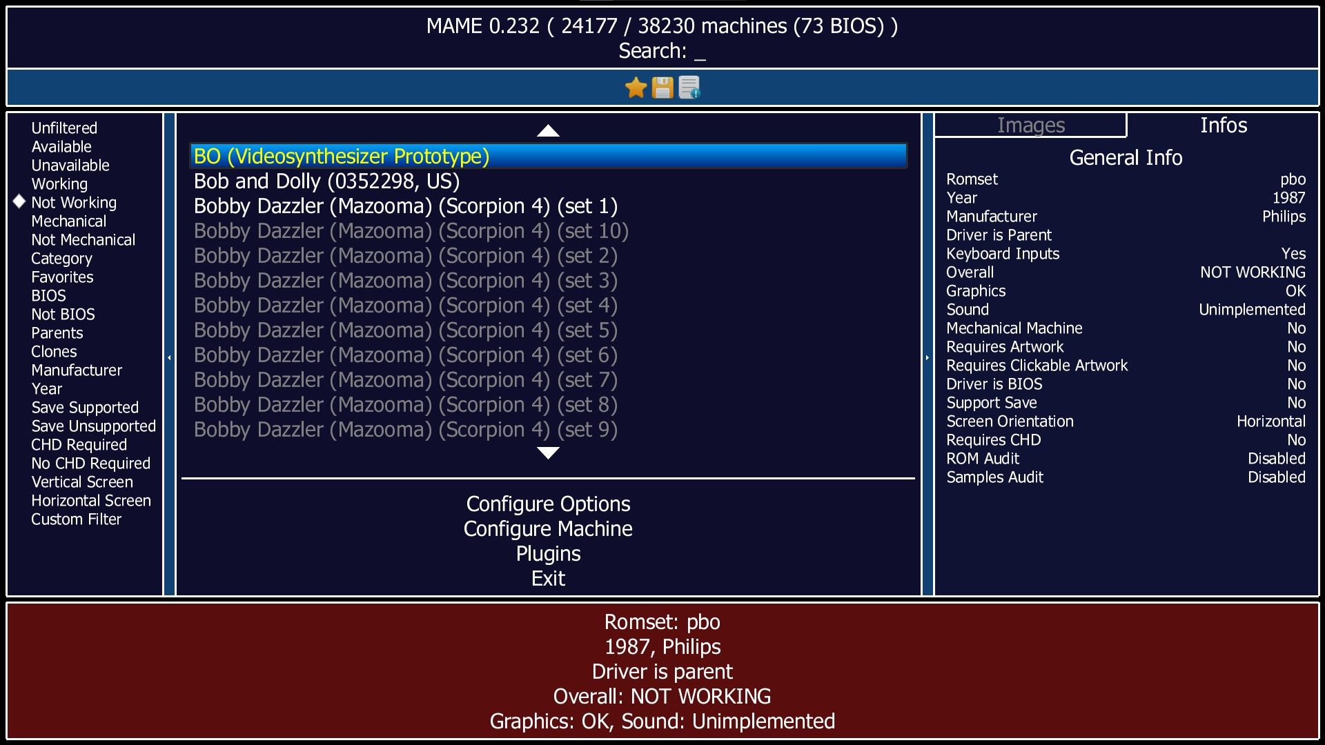
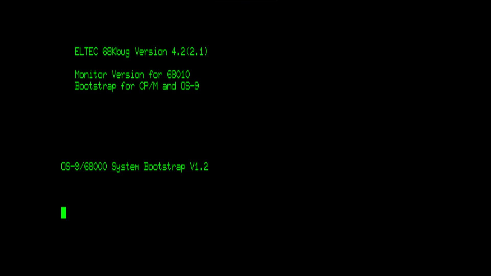
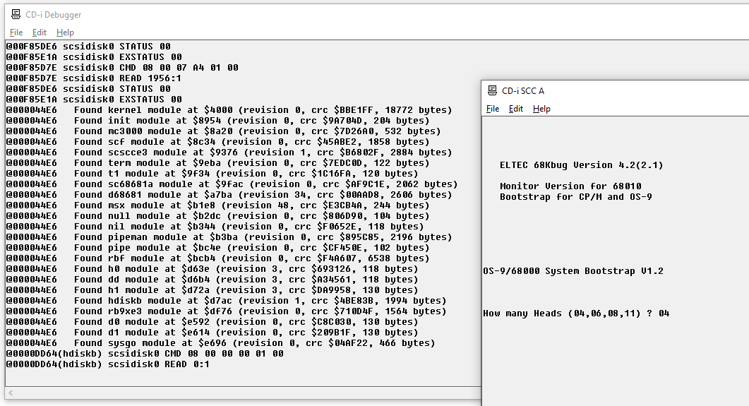
TheMogMiner, who is part of the MAME team, wrote a skeleton driver that’s now part of the latest MAME release. Currently, it can only display a few lines of text and shows a blinking cursor. The emulator gets stuck there due to it being unable to handle the Rodime's non-standard SCSI commands. You can try running it for yourself by downloading the latest MAME build and the ROM dumps at the bottom of this page.
CD-i Fan, creator of the CD-i Emulator, has also attempted to emulate this machine. He's at a point now where the OS-9 kernel gets loaded correctly from the HDD by the boot ROM, the emulation hangs when the hdiskb drive tries to load sector 0 of the HDD. The SCSI chip sends an interrupt, but for unknown reasons, it does not reach the CPU. He will try to find out the cause of this when he has the time to do so. If there's any further developments, I'll update the page.
I’d like to thank both developers for putting in the effort to try this. I’d love to see it develop further in the future.
Home Computer Museum
Since acquiring this machine, I have been considering contacting a museum about it, given its uniqueness. I eventually reached out to the Home Computer Museum in Helmond, The Netherlands, and they showed interest in the machine. Consequently, I have decided to display it there. The HCM is also home to the largest CD-i collection in the world, making it the perfect home for the machine.
Having the machine in the museum also has the advantage of making it publicly available for people to see. Additionally, it is possible to attempt further repair and tinkering at the museum. So, if you ever find yourself near Helmond, it might be worth visiting the museum!
TL:DR
In short: This system, dubbed 'Model BO Videosynthesizer Prototype' by Philips, is a Motorola 68000 VME rack which was utilized during the development phase of the Philips CD-i. This specific unit houses prototype video boards that would ultimately evolve into the SCC66470, the video chip used in Philips CD-i players. Therefore, the unit itself doesn't function as a complete CD-i system; rather, it serves as a platform for developing a specific chip utilized in the CD-i.
It operates on Microware OS-9, which can be loaded from either a floppy disk or a hard drive. The hard drive contains version 1_0D of CD-RTOS, the operating system for the CD-i, along with several miscellaneous applications presumably utilized for demonstration or testing purposes.
Although the machine powers on, it fails to boot due to a defective mainboard, which has been severely damaged by a leaking battery. Repairing it poses significant challenges due to a lack of crucial documentation, such as schematics necessary for attempting board-level repairs.
Downloads
Credits & Thanks
- JP Atkinson – Offering valuable insights and information
- David Clark - Scanning and preserving the BPCRT2 and VSR specification documents
- CD-i Fan – Much technical help and insights, emulation efforts, HDD restoration
- TheMogMiner – Creating the MAME skeleton driver
- Rosewood – Tons of valuable advice and help
- Interactive Dreams / Bas – First reporting about this unit, and helping spread the word
- Home Computer Museum - Providing a nice home for the machine
- Any other community members who showed interest and helped in various ways.